Foul-resistant condenser using microchannel tubing

a technology of microchannel tubing and condenser coil, which is applied in the direction of defrosting, domestic cooling apparatus, etc., can solve the problems of system inefficiency, dust, dirt and oil accumulation affecting refrigeration performance, and airside fouling is susceptible to

Active Publication Date: 2006-02-21
CARRIER CORP
View PDF11 Cites 70 Cited by
  • Summary
  • Abstract
  • Description
  • Claims
  • Application Information

AI Technical Summary

Benefits of technology

[0010]Briefly, in accordance with one aspect of the invention, the tube and fin condenser coil is replaced by a condenser coil having a greater number of microchannel tubes than the previous number of round tubes but, with the clearances from tube to tube being relatively large such that air side fouling is less likely to occur.
[0012]By yet another aspect of the invention, the fin density of a microtubes condenser coil is reduced to a level which will substantially eliminate the bridging of fibers between fins such that the occurrence of fouling is substantially reduced or eliminated. If the fin density is reduced to the extent that there is little or no support between the microchannel tubes, then provision is made to include a support structure, in spaced relationship between the adjacent tubes to prevent movement and / or damage thereto.

Problems solved by technology

One problem that occurs with such self-contained merchandisers is that they are often in area that is heavily trafficked by people that tend to track in debris and dirt from the outside.
This, in turn, tends to expose the condenser coil, which is necessarily exposed to the flow of air in the immediate vicinity, to be susceptible to airside fouling.
With such fouling, the accumulation of dust, dirt and oils impede refrigeration performance.
As the condenser coil fouls, the compressor refrigerant pressure rises, which leads to system inefficiencies and possibly compressor failure.
However, the greater the tube and fin densities, the more susceptible it is to being fouled by the accumulation of dirt and fiber.

Method used


Image

  • Foul-resistant condenser using microchannel tubing
  • Foul-resistant condenser using microchannel tubing
  • Foul-resistant condenser using microchannel tubing

Examples


Embodiment Construction

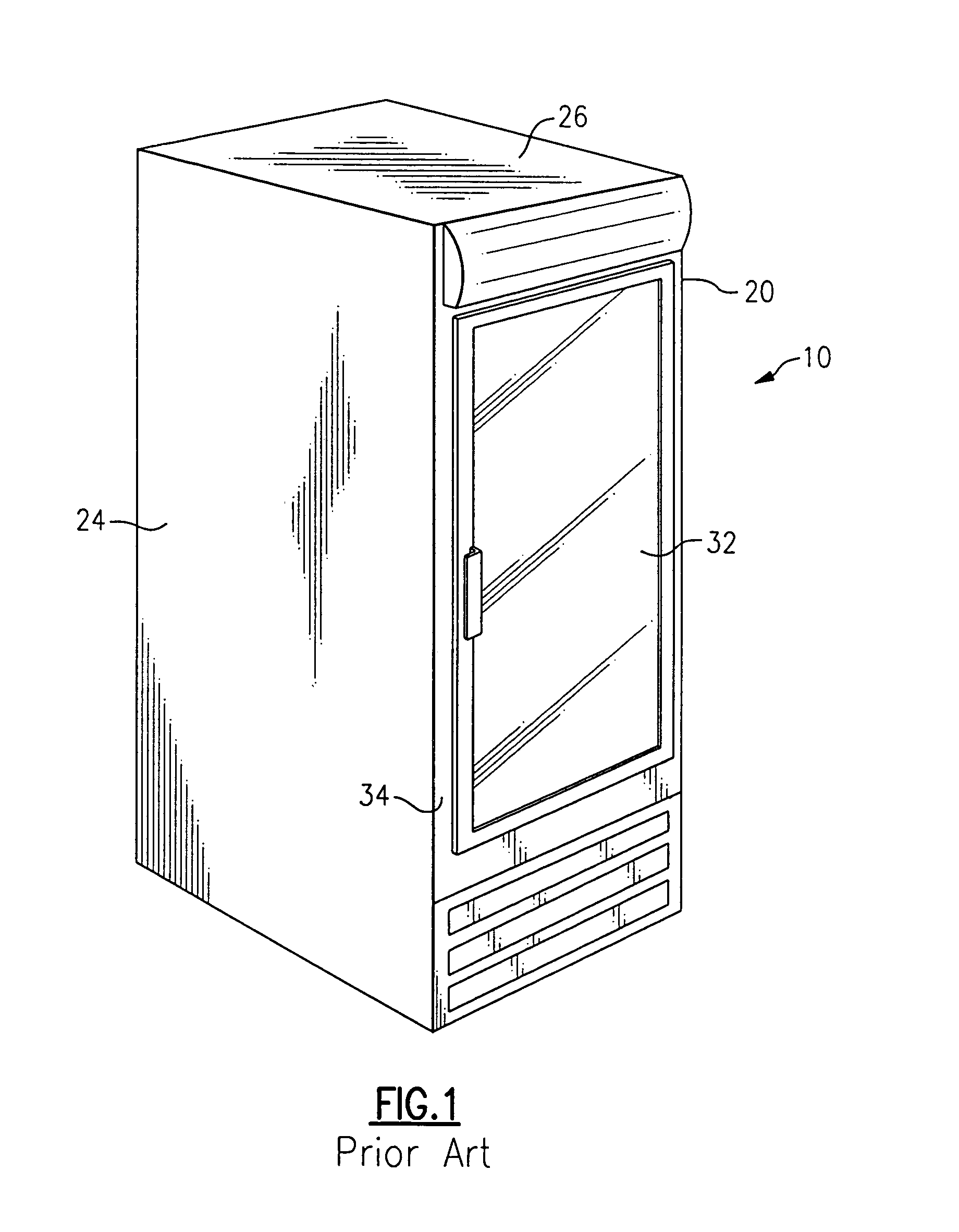
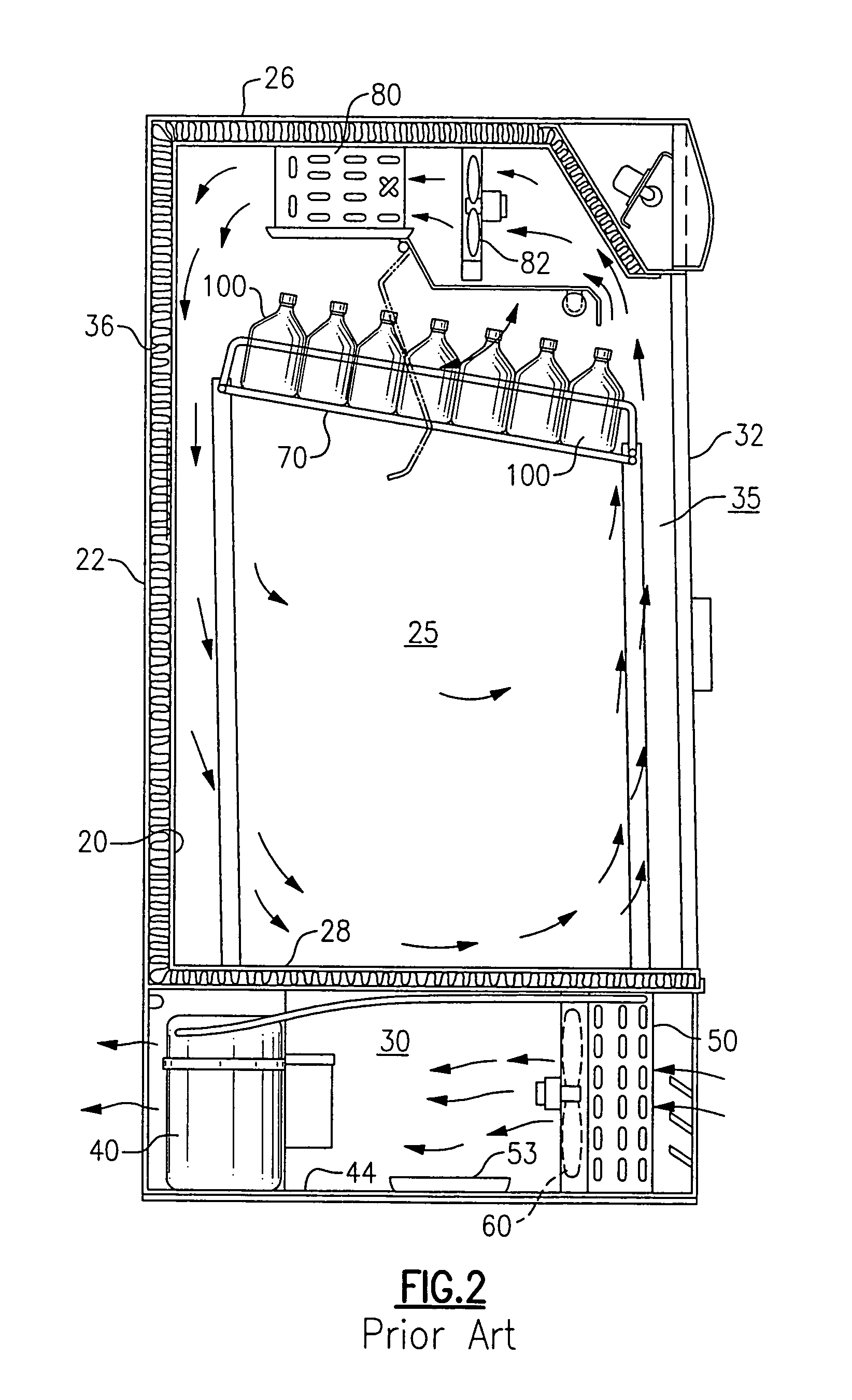
[0023]Referring now to FIGS. 1 and 2, there is depicted therein a refrigerated cold beverage merchandiser generally designated by the numeral 10. The beverage merchandiser 10 includes an enclosure 20 defining a refrigerated display cabinet 25 and a separate utility compartment 30 disposed externally of and heat insulated from the refrigerated display cabinet 25. The utility compartment may be disposed beneath the refrigerated display cabinet 25 as depicted or the utility compartment may be disposed above the display cabinet 25. A compressor 40, a condenser coil 50, a condensate pan 53 and an associated condenser fan and motor 60 are housed within the compartment 30. A mounting plate 44 may be disposed beneath the compressor 40, the condenser coil 50, and the condenser fan 60. Advantageously, the mounting plate 44 may be slidably mounted within the compartment 30 for selective disposition into and out of the compartment 30 in order to facilitate servicing of the refrigeration equipme...


PUM

PropertyMeasurementUnit
distanceaaaaaaaaaa
distanceaaaaaaaaaa
distanceaaaaaaaaaa

Abstract

A condenser coil for a refrigerated beverage and food service merchandiser includes a plurality of parallel fins between adjacent tubes. In order to reduce the likelihood of fouling by the bridging of fibers therebetween, the spacing of the fins is maintained at a distance of 0.4 to 0.8 inches apart. In one embodiment, the tubes comprise microchannel tubes, with no fins therebetween, and the spacing between the microchannel tubes is maintained in the range of 0.75 inches to optimize the heat transfer performance while minimizing the occurrence of fouling. A supporting structure is provided between microchannel tubes when no fins are included. Also, plural rows of microchannel tubes are provided with separate inlet headings and with the rows being staggered in transverse relationship to enhance the heat transfer characteristic while minimizing the likelihood of fouling.

Description

BACKGROUND OF THE INVENTION[0001]This invention relates generally to refrigerated beverage and food service merchandisers and, more particularly, to a foul resistant condenser coil therefor.[0002]It is long been the practice to sell soda and other soft drinks by way of vending machines or coin operated refrigerated containers for dispensing single bottles of beverages. These machines are generally stand alone machines that are plugged into standard outlets and include their own individual refrigeration circuit with both evaporator and condenser coils.[0003]This self serve approach has now been expanded to include other types of “plug in” beverage and food merchandisers that are located in convenience stores, delicatessens, supermarkets and other retail establishments.[0004]In such stores, cold beverages, such as soft drinks, beer, wine coolers, etc. are commonly displayed in refrigerated merchandisers for self-service purchase by customers. Conventional merchandisers of this type us...

Claims


Application Information

Patent Timeline
Patent Type & Authority Patents(United States)
IPC IPC(8): A47F3/04F25B39/04F25D17/06F25D21/12F25D21/14F25D23/00F28D1/053F28F1/32F28F9/02F28F21/06
CPCA47F3/0408F28D1/05383F28F1/32F25B39/04F28F2215/12F25B2500/01F25D17/06F25D21/14F25D23/003F25D2323/00264F25D2323/00271F25D2331/803F28D2021/007F28F21/067F28F2260/02A47F3/04F25D21/12
Inventor DADDIS, JR., EUGENE DUANECHIANG, ROBERT H. L.
Owner CARRIER CORP
Why Eureka
Try Eureka