Leakage monitoring in the hydraulic pressure area of a membrane pump

Active Publication Date: 2006-02-21
LEWA
View PDF19 Cites 13 Cited by
  • Summary
  • Abstract
  • Description
  • Claims
  • Application Information

AI Technical Summary

Benefits of technology

[0008]Thus, the invention is based on the objective of providing, for the elimination of the disadvantages described, a process of the generic type by means of which it is possible to recognize promptly increases in leakage in the hydraulic pressure area of the membrane pump so that any interruption in operation which may possibly be required can be planned promptly.

Problems solved by technology

Even if a gas discharge valve is customarily installed on the membrane pump, a certain leakage results in this valve.
Moreover, all of said structural parts of the membrane pump are subjected to a certain wear in operation.
This likewise makes itself noticeable by an increased leakage which has a disadvantageous effect on the displacement as well as on the dosing precision.
Also an undesired increase in leakage can occur due to the failure of a seal, in particular in the area of the pump piston.
Despite this, it happens relatively frequently that structural parts fail prematurely and thus cause undesirable subsequent damage which is undesirable due to the necessary interruption of operation.
These processes have, however, not proven themselves effective since they either are associated with too great an expense in construction or do not produce the desired results.

Method used


Image

  • Leakage monitoring in the hydraulic pressure area of a membrane pump
  • Leakage monitoring in the hydraulic pressure area of a membrane pump
  • Leakage monitoring in the hydraulic pressure area of a membrane pump

Examples


Embodiment Construction

[0024]In describing a preferred embodiment of the invention illustrated in the drawings, specific terminology will be resorted to for the sake of clarity. However, the invention is not intended to be limited to the specific terms so selected, and it is to be understood that each specific term includes all technical equivalents which operate in a similar manner to accomplish a similar purpose.

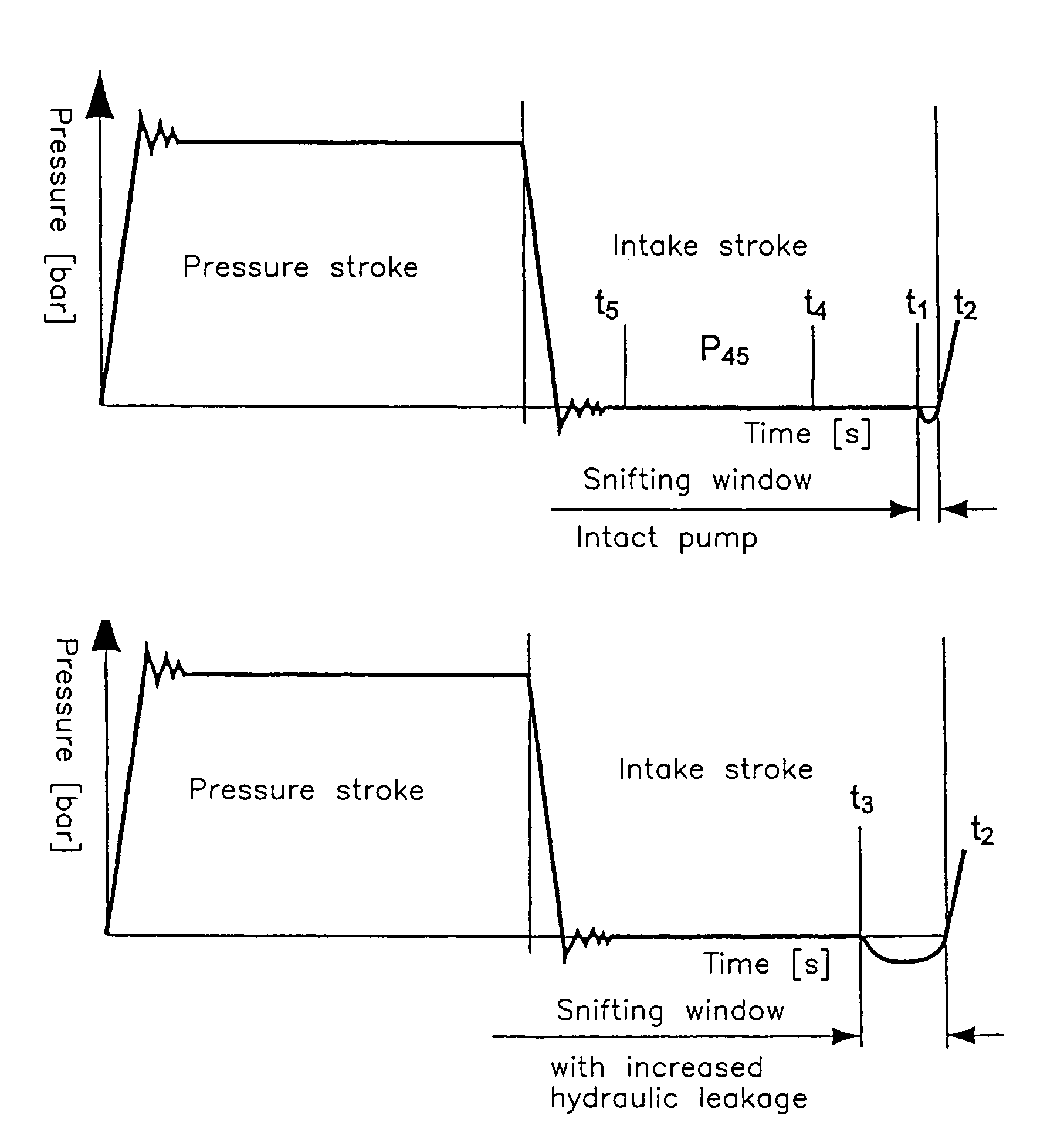
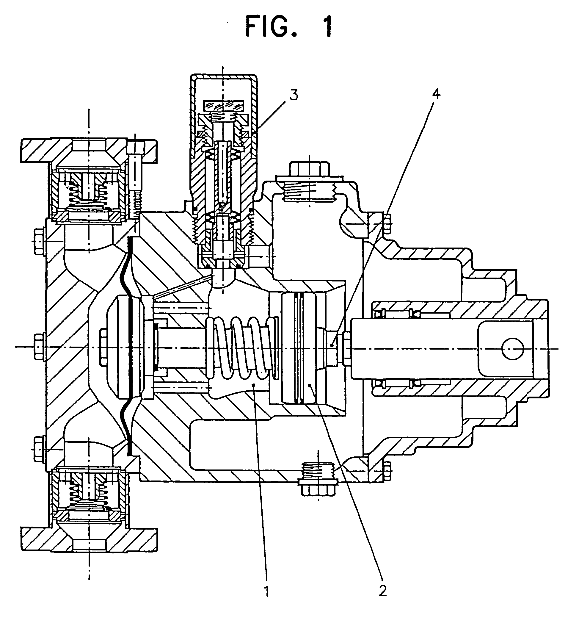
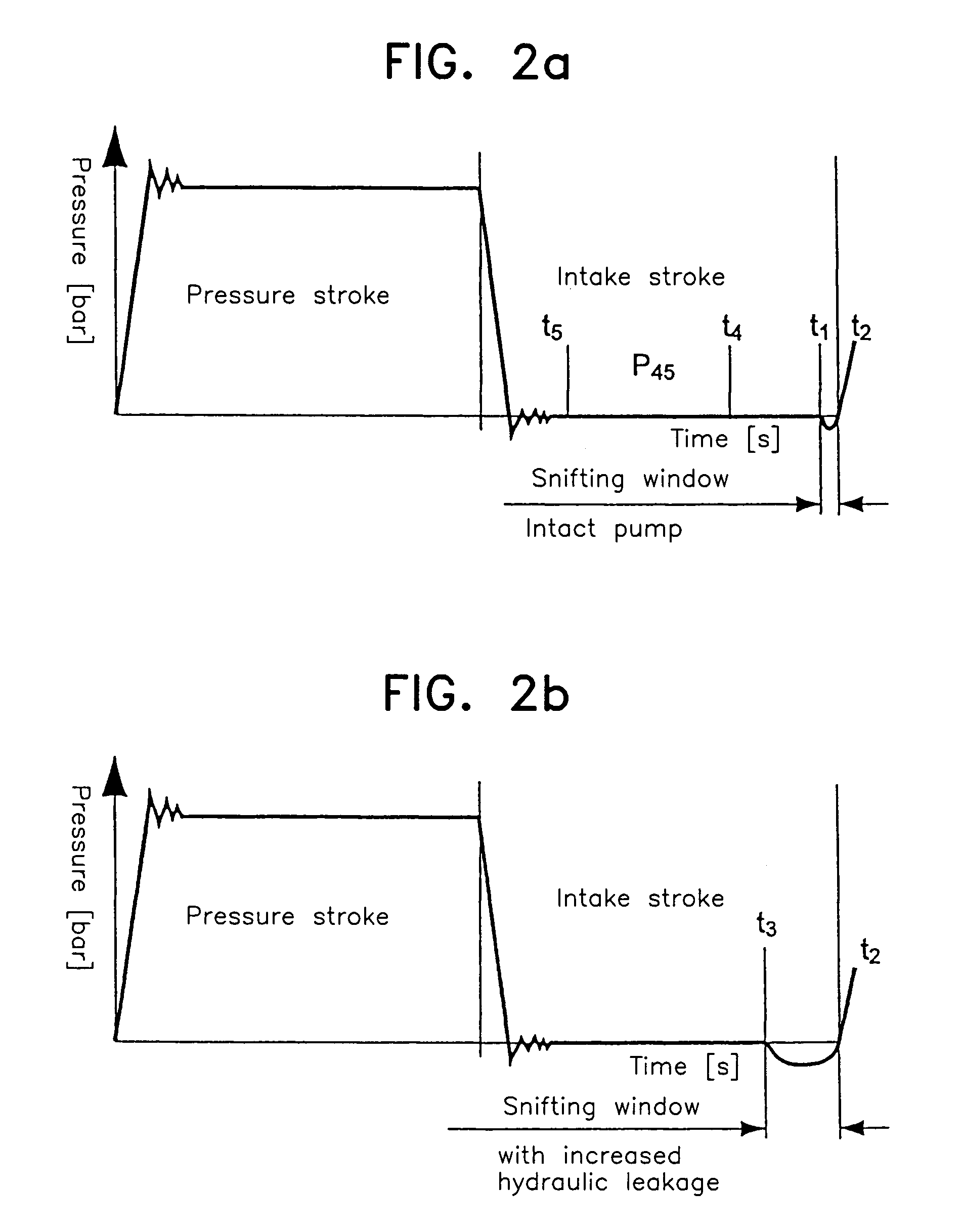
[0025]FIG. 1 shows in section a customary membrane pump whose more detailed description can be omitted because it is known, for example, from U.S. Patent Application Publication No. 2003 / 0049145, hereby incorporated in its entirety by reference. In the present case however, it is a matter of monitoring the leakage occurring in the hydraulic pressure area 1 of the pump by continuously monitoring and comparing to a reference value the point in time at which the snifting process serving for leakage compensation is initiated, where a predefined deviation between both values triggers a leakage displa...


PUM


Abstract

In a process for the monitoring of leakage in the hydraulic pressure area of a membrane pump, processing is in a manner such that the point in time (t3), at which the snifting process serving for leakage compensation is initiated, is monitored continuously and compared with a reference value (t1), where a predetermined deviation (Δt1−t3) between two values (t3 and / or t1) triggers a leakage display.

Description

FIELD OF THE INVENTION[0001]The invention relates to a process for the monitoring of leakage in the hydraulic pressure area of a membrane pump.BACKGROUND OF THE INVENTION[0002]The proper function of all the components and structural parts in the hydraulic pressure area of an, in particular hydraulically driven, membrane pump has a decisive effect on the displacement as well as on the dosing precision of such a pump.[0003]Other structural parts of the membrane pump, such as the leakage compensation valve as well as the pressure-limiting valve, are liquid-tight in new condition and have no leakage.[0004]In contradistinction thereto, the piston sealing is not liquid-tight even in new condition. Thus, depending on the embodiment of the sealing, the hydraulic fluid, and the operating parameters such as pressure, temperature, etc., there is in operation always a certain leakage which is then filled once again in the rear dead point of the piston, i.e. at the end of the intake stroke, by t...

Claims


Application Information

Patent Timeline
IPC IPC(8): G01M3/04F04B49/00F04B43/00F04B43/067
CPCF04B43/067F04B43/009
Inventor STRITZELBERGER, MICHAEL
Owner LEWA
Why Eureka
Try Eureka