Cable retraction mechanism for trigger shifters

Active Publication Date: 2006-02-21
SRAM
View PDF18 Cites 61 Cited by
  • Summary
  • Abstract
  • Description
  • Claims
  • Application Information

AI Technical Summary

Benefits of technology

[0007]It is an object of the present invention to provide a simplified shifter, with a reduced number of components, without impairing its

Problems solved by technology

Several problems are associated with these types of shifters.
Another problem is that many components are needed for the takeup and release operations.
Such

Method used


Image

  • Cable retraction mechanism for trigger shifters
  • Cable retraction mechanism for trigger shifters
  • Cable retraction mechanism for trigger shifters

Examples


Embodiment Construction

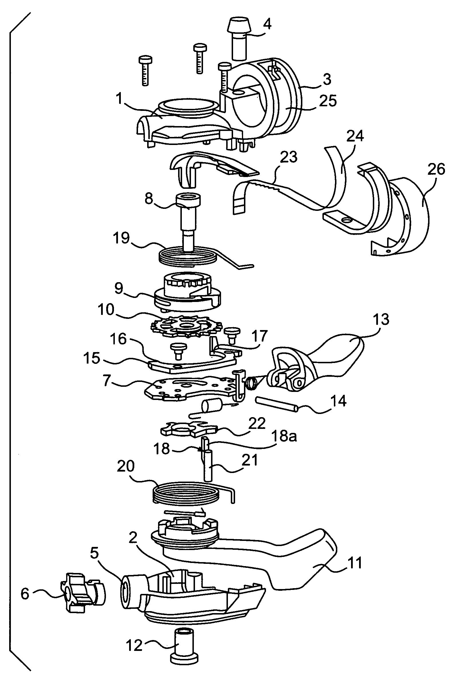
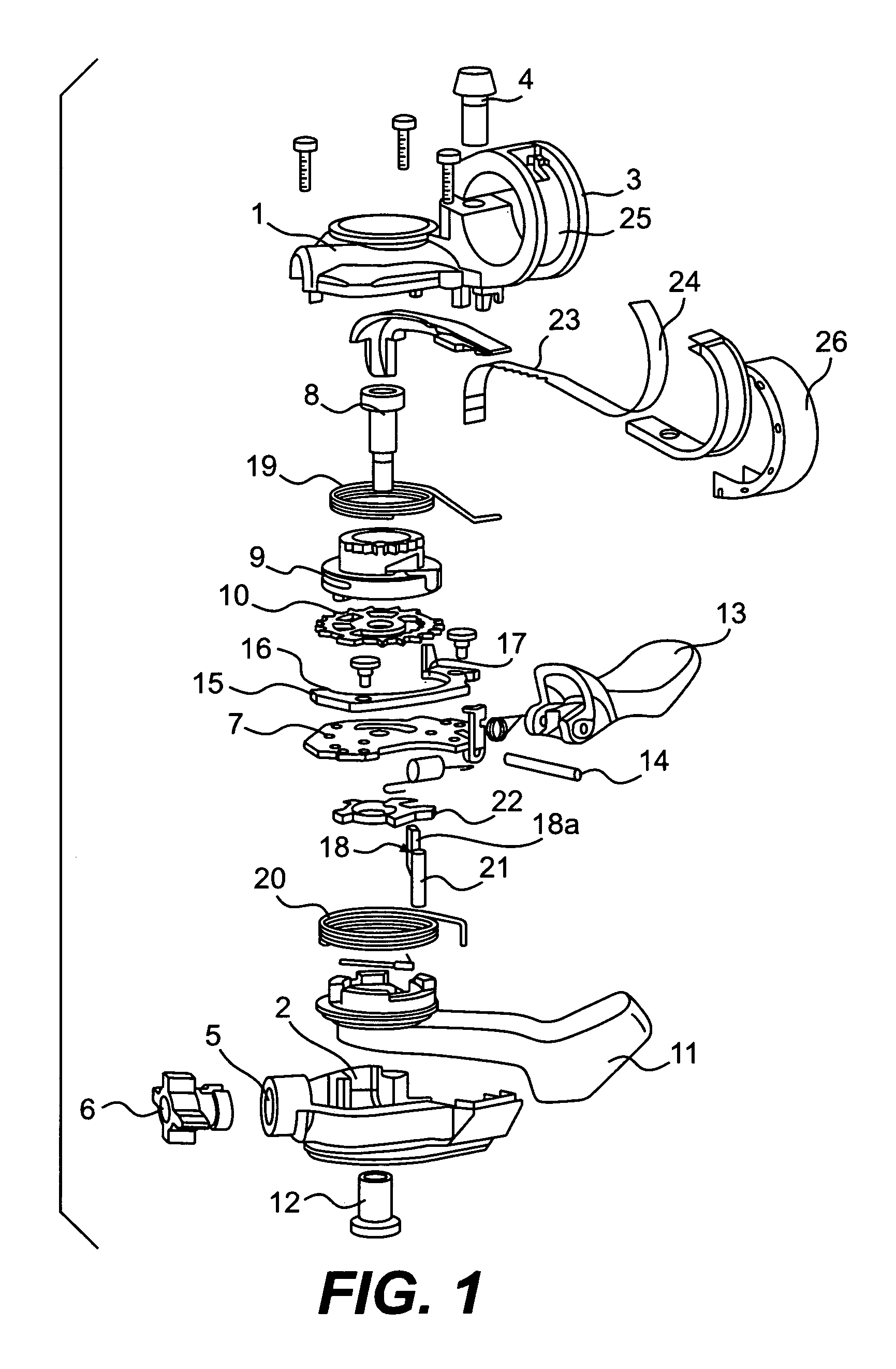
[0023]The shifter of the present invention generally includes a release mechanism, a takeup mechanism, a cable spool and a gear indicator. A housing 1 and an enclosing element 2 encase the release mechanism, the takeup mechanism and the gear indicator. The housing 1 preferably includes an integrated handlebar attachment including a handlebar clamp 3 and a clamp screw 4. The enclosing element 2 preferably has a thread 5 for receiving an adjustment screw 6 to adjust a shifting cable (not shown). The enclosing element 2 is produced from plastic, without additional machining, and is bolted to the housing 1.

[0024]A cable spool 9 is mounted on a central shaft and axially immobilized by a shaft nut 12. One end of the shifting cable is attached to the cable spool 9 for winding and unwinding thereon, the other end to a bicycle transmission.

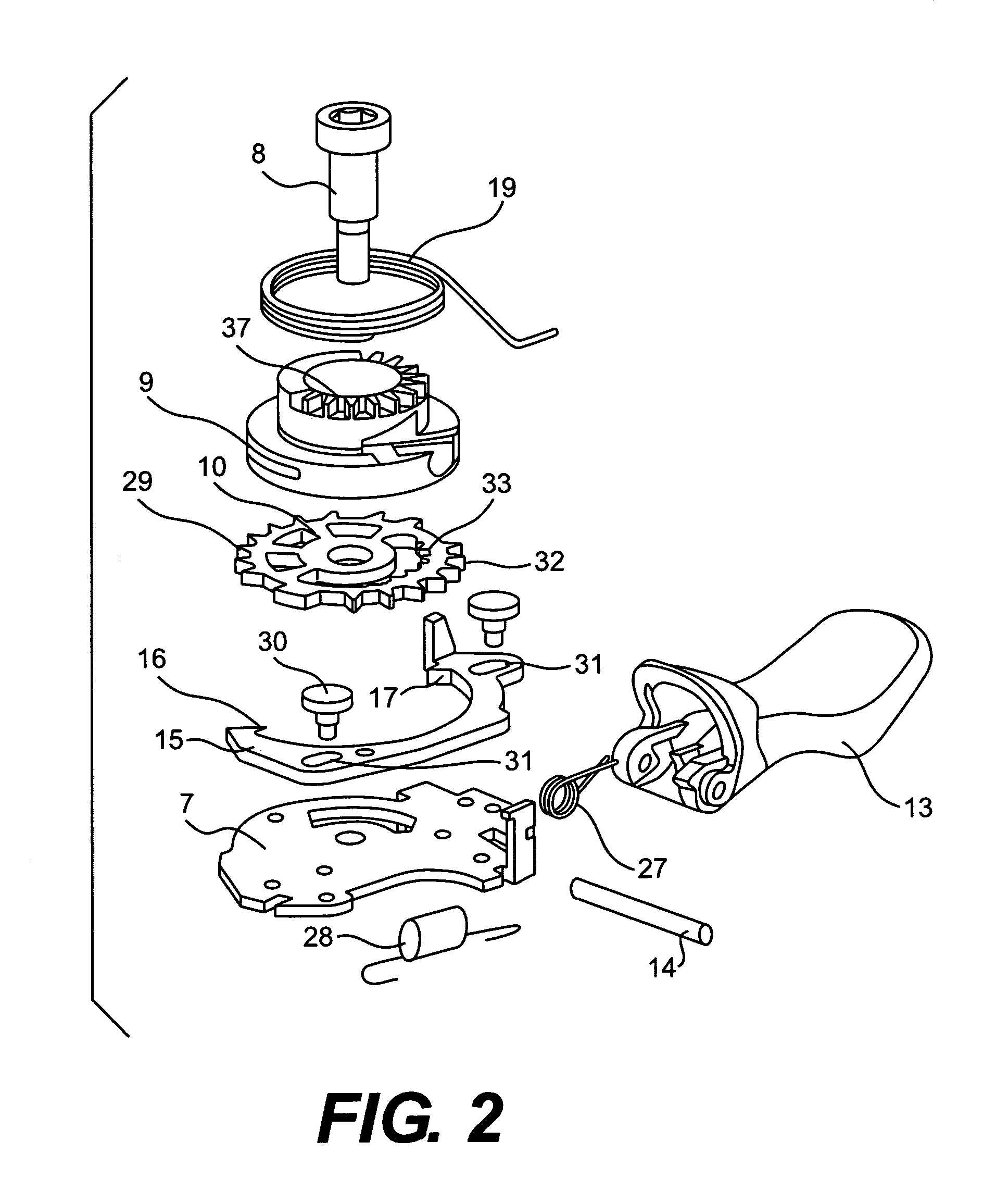
[0025]The release and takeup mechanisms are arranged around a carrier plate 7 and about the central shaft 8. Referring to FIGS. 1 and 2, the release mecha...


PUM


Abstract

A bicycle shifter having a housing mountable to a handlebar, a takeup mechanism for pulling a shift cable and a release mechanism for releasing the shift cable. The takeup mechanism includes a takeup tooth segment, a takeup pawl and an actuation element. The release mechanism includes retaining and locking tooth segments, retaining and locking pawls and a release element. The takeup, retaining and locking tooth segments are arranged on one disk element.

Description

BACKGROUND OF INVENTION[0001]The present invention relates to bicycle shifters and more particularly to a bicycle shifter having tooth segments for takeup, retention and release of a shifting cable that are arranged on one disk element.[0002]Trigger shifters are typically used to pull and release a spring-loaded shifting cable, and biased to return to their original positions after they are actuated. Trigger shifters are disclosed in patents EP 0 361 335 B1 and U.S. Pat. No. 6,095,010. The shifters disclosed in these patents have two levers, a takeup lever to wind the spring-loaded shifting cable and a release lever to disengage positioning and retaining devices to release or unwind the shifting cable. The takeup lever rotates a takeup or cable spool by actuating a pawl biased in an engagement direction. The takeup spool is preloaded in the unwinding direction by a return spring acting on the shifting cable. The positioning device retains the takeup spool in a particular shift posit...

Claims


Application Information

Patent Timeline
IPC IPC(8): F16C1/10G05G1/00B62M25/04
CPCB62M25/04B62M25/045Y10T74/214Y10T74/20438Y10T74/2133Y10T74/20287Y10T74/2136Y10T74/2028
Inventor WESSEL, ROBERTWEISS, MARTIN
Owner SRAM
Why Eureka
Try Eureka