High frequency oscillator ventilator

a high frequency oscillator and ventilator technology, applied in the direction of valve details, valve arrangement, operating means/releasing devices, etc., can solve the problem of removing the large moveable element of the known hfo ventilator, and avoid the risk of energy loss in expansion, reduce the risk of expansion, and increase the design flexibility

Inactive Publication Date: 2006-02-21
MAQUET CRITICAL CARE
View PDF16 Cites 44 Cited by
  • Summary
  • Abstract
  • Description
  • Claims
  • Application Information

AI Technical Summary

Benefits of technology

[0010]By generating oscillations by alternately introducing and withdrawing a volume of additional gas sufficient to provide a desired tidal volume to the patient's airways, the disadvantage of reciprocating the large moveable element of the known HFO ventilator is removed.
[0011]Preferably, the oscillator is adapted to introduce the additional gas proximal the opening in the first gas conduit which is intended for connection with the patient's airways. This reduces dead-space, allows a more flexible tubing to be used for the remainder of the conduit away from the opening without the risk of energy being lost in expanding and contracting the tubing, and permits smaller volumes of gas to be used in order to generate the desired pressure oscillations.
[0012]Conveniently, the additional gas may be introduced by a pulse generator via a second conduit which opens into the first and its removal may be accomplished by a separate device via the first, the second or even a third conduit. The increased design flexibility provided by providing separate means for introducing and for removing gas also allows each of the means to be optimised for its intended purpose.

Problems solved by technology

By generating oscillations by alternately introducing and withdrawing a volume of additional gas sufficient to provide a desired tidal volume to the patient's airways, the disadvantage of reciprocating the large moveable element of the known HFO ventilator is removed.

Method used


Image

  • High frequency oscillator ventilator
  • High frequency oscillator ventilator
  • High frequency oscillator ventilator

Examples


Embodiment Construction

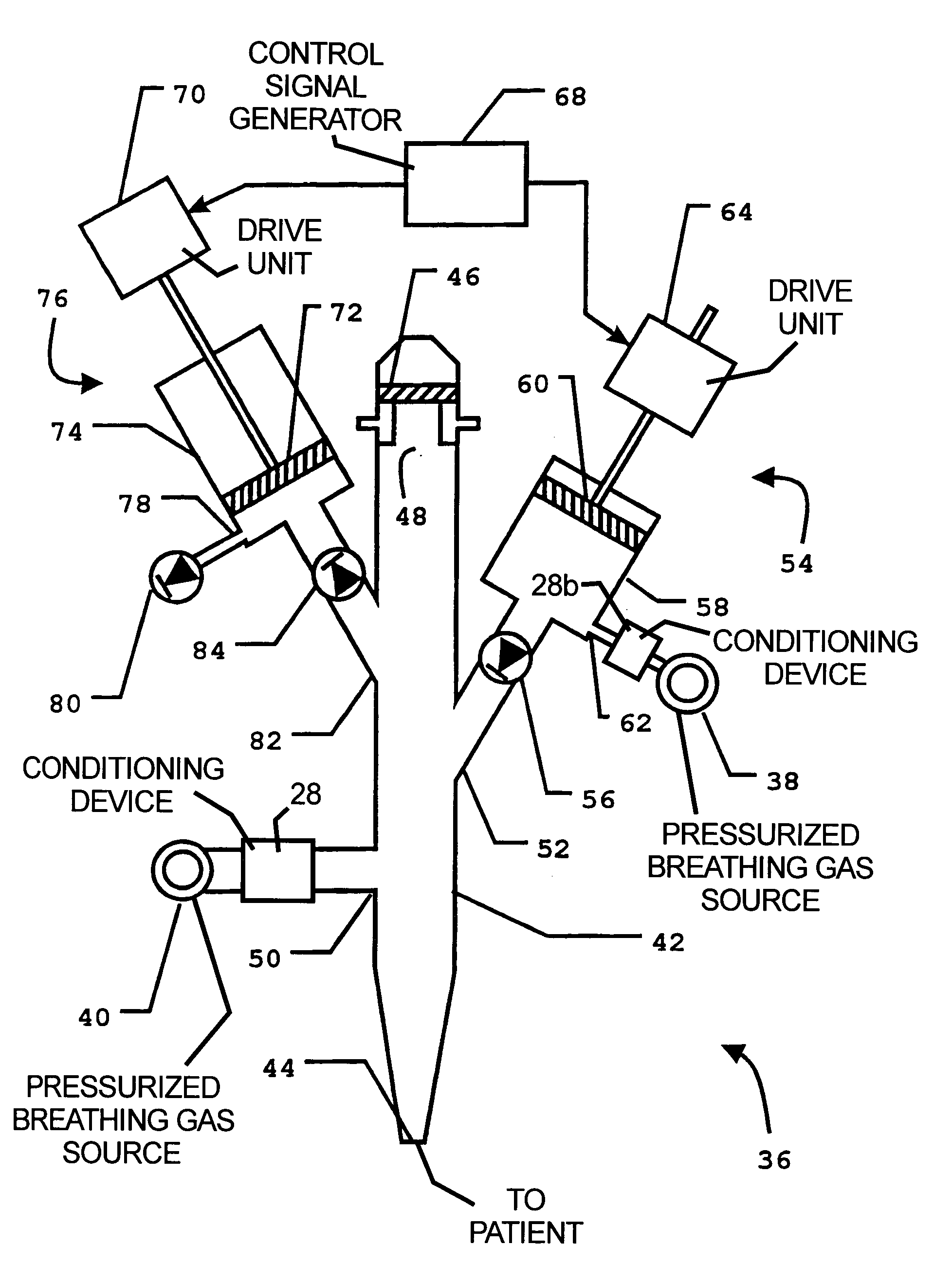
[0016]In FIG. 1, an HFO ventilator 2 is shown in operative connection to a source of pressurized breathing gas 4. The HFO ventilator 2 is configured to utilize the source of breathing gas 4 both as a bias flow and as a source of an additional gas, as will be described below. The source of breathing gas 4 may conveniently be a conventional mechanical ventilator adapted to provide a continuous flow output.

[0017]The HFO ventilator 2 is provided with a primary conduit 6 that has a patient opening 8 at one end which is intended to be placed in gas communication with a patient's airways, for example by connection to a conventional endotracheal tube (not shown). A vent opening 10 is also provided in the primary conduit 6 through which gas may be vented to atmosphere (as shown) or to a known gas recovery means (not shown). A one-way valve 12 is disposed within the primary conduit 6, proximal the vent opening 10 and is configured to prevent gas entering the conduit 6 through the vent opening...


PUM


Abstract

A high-frequency oscillator ventilator has a first gas conduit with an opening for gas connection with a patient's airways and a bias gas flow inlet and a bias flow outlet disposed to define therebetween a flow path for a bias gas within the first conduit. An oscillator operable to alternately introduce a volume of additional gas from a source into, and to withdraw at least the same volume of gas from, the first gas conduit, thereby inducing pressure oscillations in gas within the first conduit to move gas along a path intersecting the flow path for a bias gas alternately into and out of the opening at a predetermined high-frequency dependent on the output of a control signal generator.

Description

BACKGROUND OF THE INVENTION[0001]1. Field of the Invention[0002]The present invention relates to a high frequency oscillator (HFO) ventilator.[0003]2. Description of the Prior Art[0004]High-frequency (HF) ventilators may be classified as belonging to one of two categories, namely the high-frequency jet (HFJ) ventilator and the HFO ventilator.[0005]The HFJ ventilator operates to fully ventilate a patient by supplying jet pulses of breathing gas to a patient's airways. These jet pulses are typically supplied through a narrow cannula at a frequency of between 2.5 Hz and 10 Hz, at a pressure of between 0.2 bar and 2.7 bar and with a tidal volume of around 2 to 5 milliliters (ml) per kilogram (kg) body weight of a patient. This high pressure jet pulse causes the lungs to expand during an inspiration phase in which the desired tidal volume is supplied. The expiration phase is essentially passive and results from the natural compliance of the lungs which tends to collapse them and expel th...

Claims


Application Information

Patent Timeline
Patent Type & Authority Patents(United States)
IPC IPC(8): A61M16/00A62B7/00A61M16/12
CPCA61M16/127A61M16/0096
Inventor BENNARSTEN, JOHANRYDGREN, GORANSTROM, CHRISTER
Owner MAQUET CRITICAL CARE
Why Eureka
Try Eureka