Locking window device

a window locking and locking technology, applied in the direction of fastening means, mechanical devices, carpet fasteners, etc., can solve the problems of increasing the risk of damage to the cam, affecting the safety of the cam, and requiring exact alignment of the finished product in the current lock construction, so as to prevent unwanted movement of the cam, reduce the risk of damage, and reduce the effect of damag

Inactive Publication Date: 2006-02-21
LAWRENCE BARRY G
View PDF13 Cites 60 Cited by
  • Summary
  • Abstract
  • Description
  • Claims
  • Application Information

AI Technical Summary

Benefits of technology

[0009]It is a further object of the present invention to provide an improved window locking mechanism. The window includes a window frame with at least one sash movable between open and closed positions.
[0012]The housing is constructed to form a recess to fit enclosably over at least part of the keeper. Once the housing and the keeper are in place, the handle rotates the cam into a cavity in the keeper. Compared with current window lock design, this interaction distributes the locking force across a greater surface area of the keeper and the housing. Additionally, this design does not push or pull the sashes out of alignment. Collectively, these result in an improved window unit having a locking device that provides greater security and efficiency.
[0013]The improved locking device further includes a one-piece circular washer having spring-like properties in the vertical and horizontal directions, relative to the window sash. The washer is designed to fit in an inset defined by the housing and is held in place by the top of the cam. The handle is mounted through a hole about in the center of the washer. The spring-like properties of the washer provide slight resistance to movement and aid in the audible indication of the unlocked and locked positions. These features prevent unwanted movement of the cam by removing excess “play” or “slack” in the movement and serves to “snap” the handle gently against the housing to provide an audible status indication.

Problems solved by technology

Several problems exist with current sash lock technology.
First, the physical force exerted on the engaging surfaces creates an undue amount of stress on all parts of the lock.
Failures often occur when the cam breaks at its point of intersect with the tooth-like protrusion or the handle, when the keeper breaks in the vicinity of the tooth-like protrusion, or when the handle breaks during operation.
Second, current lock construction demands exacting alignment of the finished product when installed.
If this is not achieved, the security function of the window is compromised (i.e., the mechanism will not engage the keeper and thus lock the window).
If only partial alignment is achieved, undue stress will be placed on window and lock components, leading to failure of the window and the lock.
Third, the surface engagement mechanism used by current sash locks can push the window sashes away from one another.
Conversely, the mechanism can pull the sashes together with excessive force.
The result in either case can be misalignment of the window sashes when the window is locked.
This compromises the safety and energy efficiency functions of the window.

Method used


Image

  • Locking window device
  • Locking window device
  • Locking window device

Examples


Embodiment Construction

[0023]Typical embodiments of the claimed invention are described in detail herein. It will be understood that the illustrations are for describing the typical embodiment of the invention and are not intended to limit the invention. Furthermore, such terms as “upward,”“downward,”“front,”“back,”“forward,”“rearward,”“top,”“bottom,” and the like are used for convenience and are not to be construed as limiting. Like numbers refer to like elements throughout the drawings and specification.

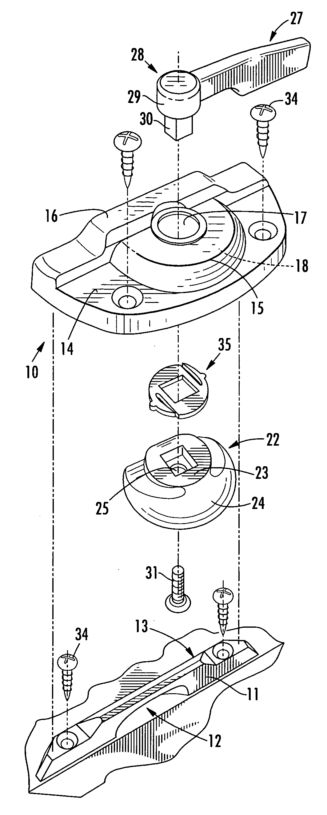
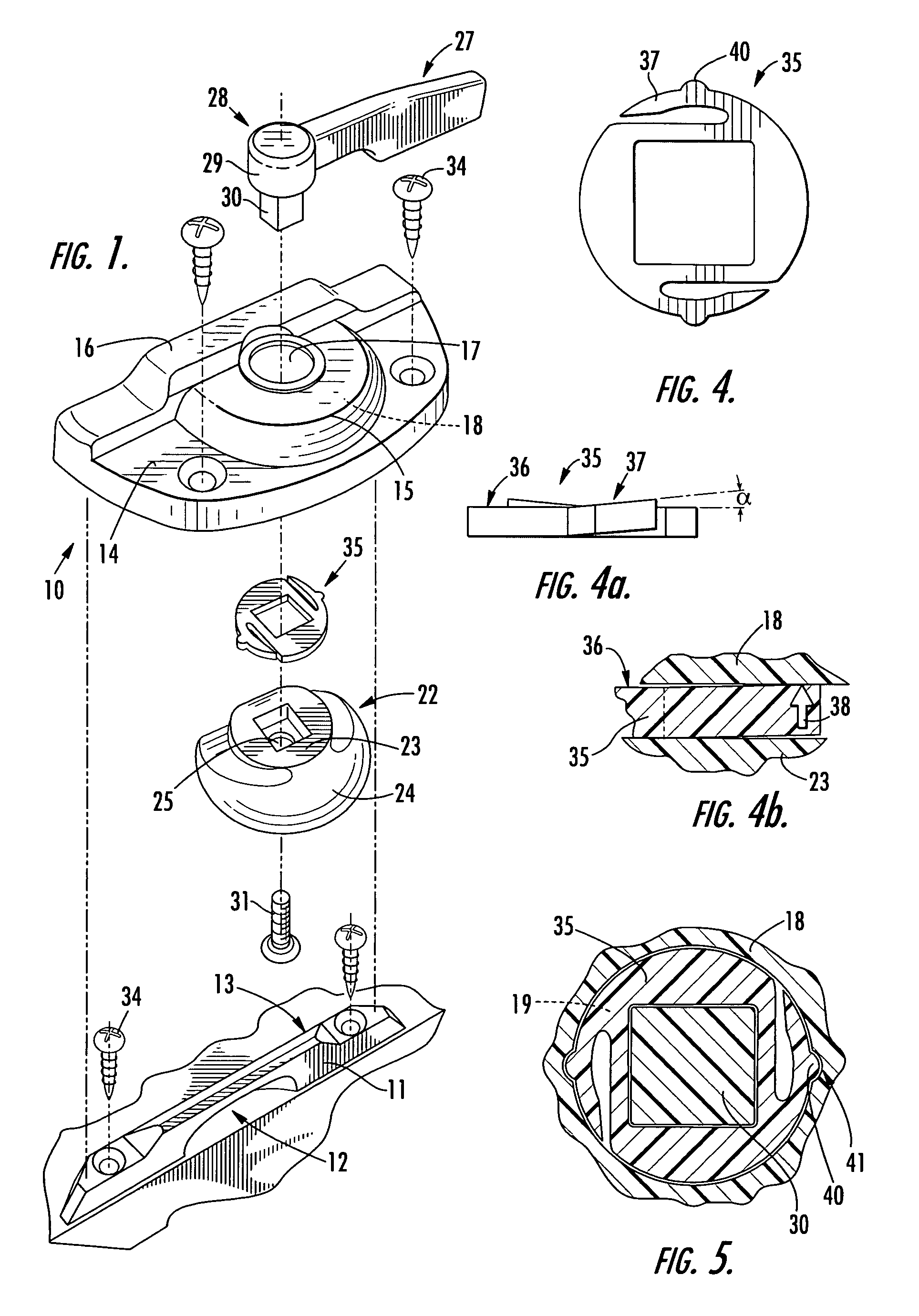
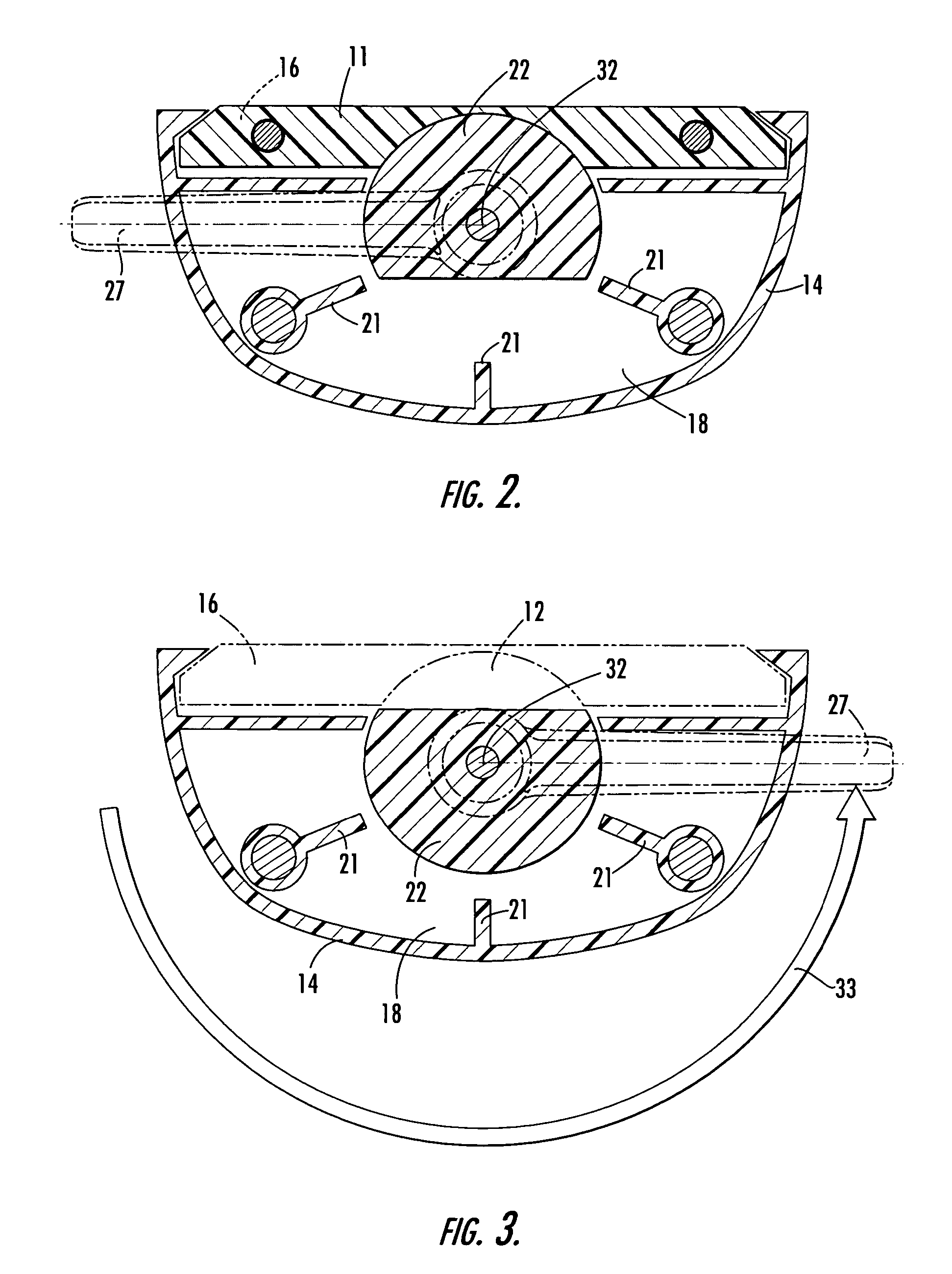
[0024]In one aspect, the invention is a locking device 10. Referring to FIG. 1, the locking device 10 includes a keeper 11 (or striker) defining an internal cavity 12, a housing 14 having an interior 18 that defines a keeper recess 16, and a cam 22 rotatively positioned within the housing 14. Rotative positioning of the cam 22 refers to the position of the cam relative to the internal cavity 12 of the keeper. The cam may be rotatively positioned between a locked position (FIG. 2) and an unlocked position...


PUM


Abstract

An improved locking device for sash-type windows is provided. The locking device includes a keeper defining an internal or keeper cavity, a housing defining first and second tier-recess combinations, a solid cam rotatively positioned within the first tier-recess combination, and a washer positioned between the housing interior and the flat top portion of the cam. The second tier-recess combination, or keeper recess, is defined by at least a portion of the housing that engages the keeper, such that the keeper is nestable within (wholly or partially enclosed by) the second tier-recess combination. Attempting to force the cam past the keeper cavity when the locking mechanism is locked results in the distribution of the force across the surface area of the keeper recess. The first tier-recess combination further defines an aperture for mounting a handle to engage and operate the cam.

Description

FIELD OF THE INVENTION[0001]The present invention relates to a novel window locking device having improved function, including improved strength, security, and durability.BACKGROUND OF THE INVENTION[0002]Closure mechanisms and locks for windows are known in the art. For many years, windows have utilized various mechanisms to secure closure, primarily for safety, security, and energy efficiency. In particular, double hung window assemblies, which have an upper sash window and a lower sash window mounted within a common frame, have typically used sash locks, which draw the upper and lower sashes together to prevent sliding.[0003]Such sash locks generally incorporate a housing mounted on one sash and a keeper mounted on the opposite sash. A lever or actuator arm handle is mounted atop the housing. The handle serves to move an internal mechanism between locked and unlocked positions. Specifically, the surface of the cam engages a tooth-like protrusion of the keeper in the locked positio...

Claims


Application Information

Patent Timeline
Patent Type & Authority Patents(United States)
IPC IPC(8): E05C3/04E05B17/00E05B65/08E05C7/00
CPCE05B65/0841E05C3/046E05B17/0083Y10S292/07Y10S292/35Y10S292/20Y10S292/47E05C2007/007Y10T292/1041Y10T292/1039
Inventor LAWRENCE, BARRY G.
Owner LAWRENCE BARRY G
Why Eureka
Try Eureka