Cantilevered gantry apparatus for x-ray imaging

a cantilevered gantry and x-ray technology, applied in the field of cantilevered gantry apparatus for x-ray imaging, can solve the problems of procedurally cumbersome, limited field of view, and previous attempts to simply not address the true need

Inactive Publication Date: 2006-02-21
MEDTRONIC NAVIGATION INC
View PDF78 Cites 317 Cited by
  • Summary
  • Abstract
  • Description
  • Claims
  • Application Information

AI Technical Summary

Problems solved by technology

This is mainly due to the cost, size, and expertise required to operate traditional three-dimensional devices.
Previous attempts simply do not address the true need, which is to maintain a sizable volume while meeting a level of expected image quality.
These C-arm based attempts have a limited field of view, are procedurally cumbersome and have an inherent limit to the image quality.
However, these so-called “mobile CT scanners” are characterized by the elevated dosing level of a traditional fixed CT scanner, they are difficult to maneuver, and they are incapable of performing 2D imaging when that is all that is needed.
In general, the fluoroscopic C-arm attempts meet the criteria of mobility and flexibility, but fall short on image quality and image volume.
The “mobile CT scanner” attempts meet the criteria of image volume and quality, but fail to address the practical issues of usability and cost.
Additionally, state of the art CT scanners are incapable of translating and tilting in the same fashion of mobile fluoroscopy systems.
This is mainly due to the fact that current tomographic scanners are not mobile in a practical manner.
The inability to move a CT scanner with the same degrees of freedom of mobile C-arms has hindered the acceptance and use of mobile three-dimensional imaging.
This has limited the value of three-dimensional computed tomographic imaging to areas mainly as a diagnostic tool in the Radiology Department.

Method used


Image

  • Cantilevered gantry apparatus for x-ray imaging
  • Cantilevered gantry apparatus for x-ray imaging
  • Cantilevered gantry apparatus for x-ray imaging

Examples


Embodiment Construction

[0022]A description of preferred embodiments of the invention follows.

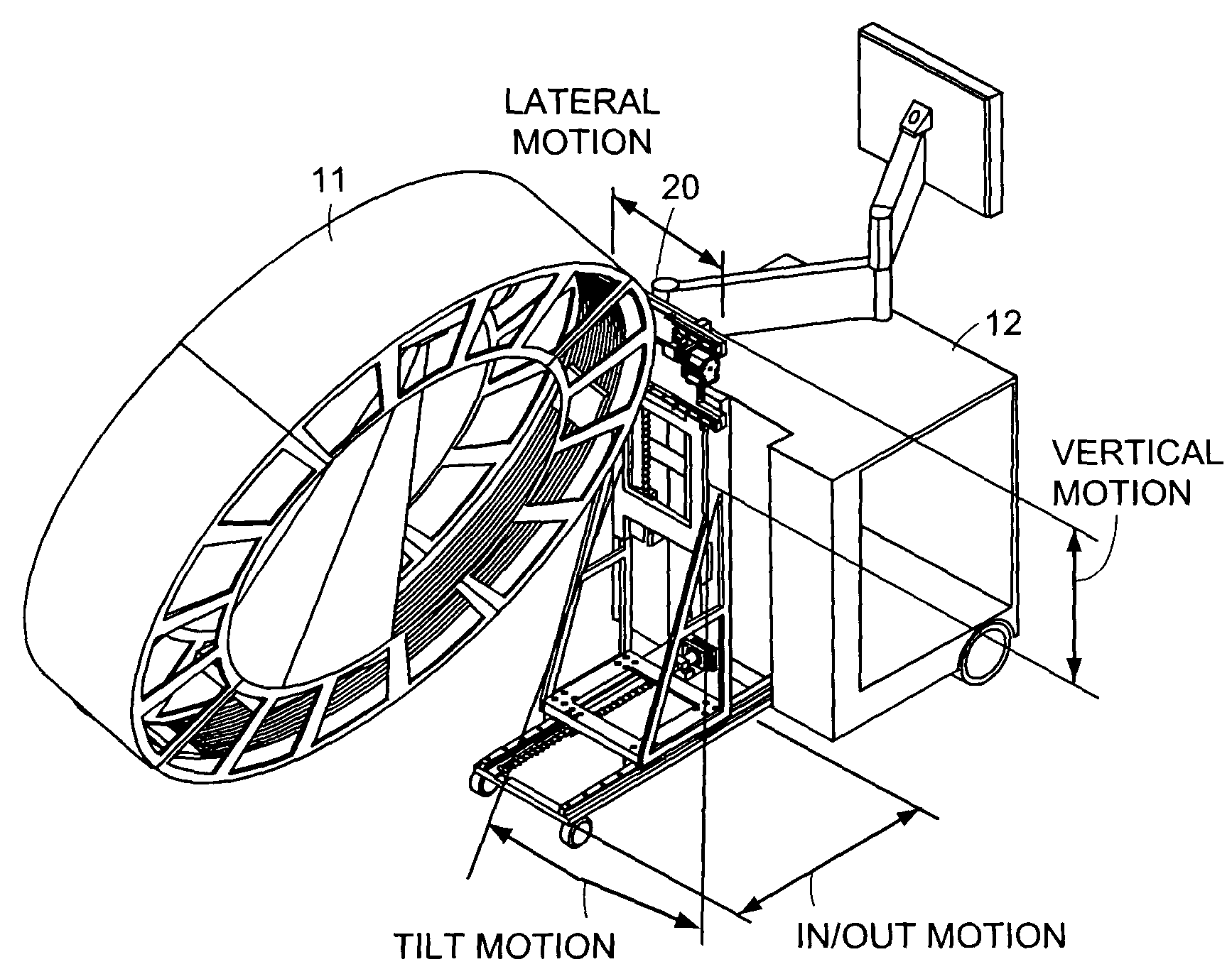
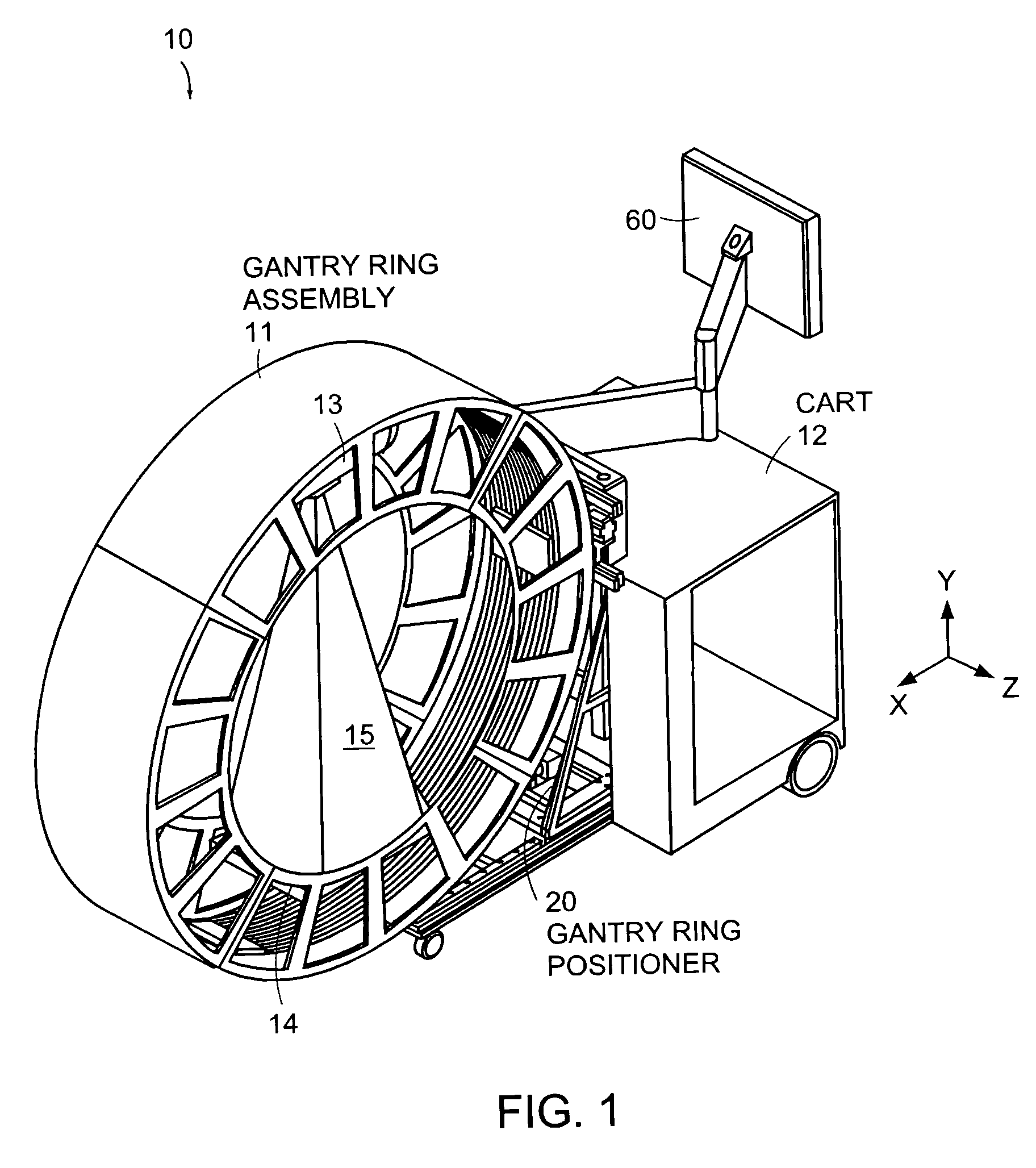
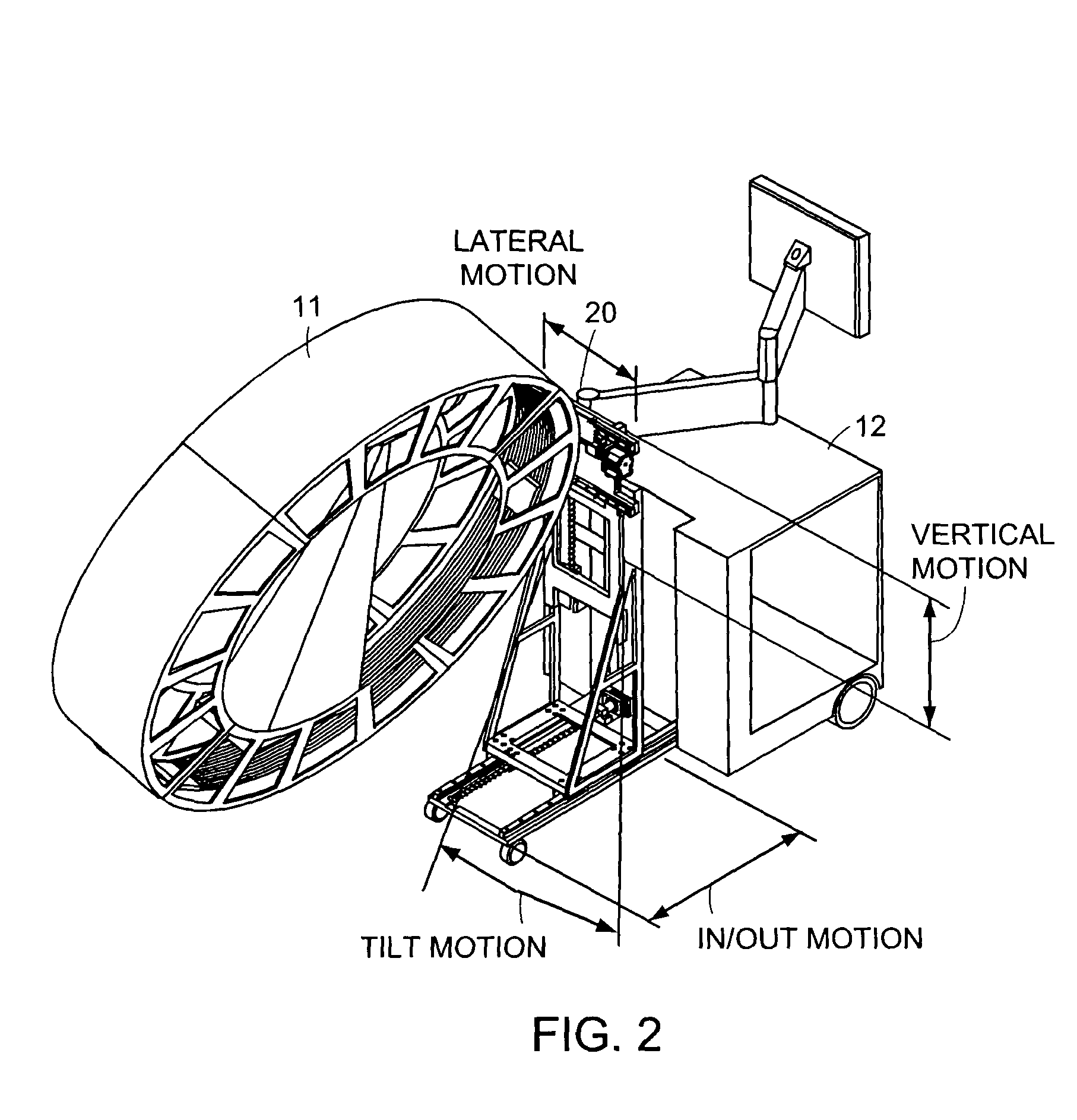
[0023]FIG. 1 is a schematic diagram showing an x-ray scanning system 10 in accordance with one embodiment of the invention. The x-ray scanning system 10 includes a gantry 11 secured to a support structure, which could be a mobile or stationary cart, a patient table, a wall, a floor, or a ceiling. As shown in FIG. 1, the gantry 11 is secured to a mobile cart 12 in a cantilevered fashion via a ring positioning unit 20. As described in further detail below, the ring positioning unit 20 can translate and / or tilt the gantry 11 with respect to the support structure to position the gantry 11 in any number of imaging positions and orientations.

[0024]The mobile cart 12 of FIG. 1 can optionally include a power supply, an x-ray power generator, and a computer system for controlling operation of the x-ray scanning device and for performing image processing, storage of x-ray images, or other data processing functions. In a pre...


PUM


Abstract

An x-ray scanning imaging apparatus with a rotatably fixed generally O-shaped gantry ring, which is connected on one end of the ring to support structure, such as a mobile cart, ceiling, floor, wall, or patient table, in a cantilevered fashion. The circular gantry housing remains rotatably fixed and carries an x-ray image-scanning device that can be rotated inside the gantry around the object being imaged either continuously or in a step-wise fashion. The ring can be connected rigidly to the support, or can be connected to the support via a ring positioning unit that is able to translate or tilt the gantry relative to the support on one or more axes. Multiple other embodiments exist in which the gantry housing is connected on one end only to the floor, wall, or ceiling. The x-ray device is particularly useful for two-dimensional multi-planar x-ray imaging and / or three-dimensional computed tomography (CT) imaging applications

Description

RELATED APPLICATION[0001]This application claims the benefit of U.S. Provisional Application No. 60 / 388,063, filed Jun. 11, 2002, the entire teachings of which are incorporated herein by reference.BACKGROUND OF THE INVENTION[0002]Healthcare practices have shown the tremendous value of three-dimensional imaging, mainly as a diagnostic tool in the Radiology Department. Other areas of care, including the operating room, intensive care departments and emergency departments, rely on two-dimensional imaging (fluoroscopy, ultrasound, 2-D mobile X-ray) as the primary means of diagnosis and therapeutic guidance. This is mainly due to the cost, size, and expertise required to operate traditional three-dimensional devices. Moreover, radiologic quality CT scanners have been designed to maximize image quality at the expense of mobility. Truly practical and mobile imaging solutions for “non-radiology departments” capable of performing both 2D and 3D imaging in the same device have yet to be devel...

Claims


Application Information

Patent Timeline
Patent Type & Authority Patents(United States)
IPC IPC(8): F21V33/00A61B6/00A61B6/03
CPCA61B6/035A61B6/4405A61N5/1082A61N5/10A61N5/1081A61B6/4447G01N2223/419
Inventor GREGERSON, EUGENE A.GRANT, RICHARD K.JOHNSON, NORBERT J.
Owner MEDTRONIC NAVIGATION INC
Why Eureka
Try Eureka