Intervertebral prosthesis

a technology for intervertebral prosthesis and prosthesis core, which is applied in the field of intervertebral prosthesis, can solve the problems of difficult operation for operating surgeon to insert the prosthesis core into the seat, the prosthesis core cannot be inserted between the cover plates, and the interlocking is in principle unsafe, so as to avoid complications. the effect of operation

Inactive Publication Date: 2006-02-21
CERVITECH INC
View PDF12 Cites 249 Cited by
  • Summary
  • Abstract
  • Description
  • Claims
  • Application Information

AI Technical Summary

Benefits of technology

[0004]The object of the invention is therefore to make available an intervertebral prosthesis of the type described, in which the prosthesis core is held securely in the prosthesis and does not complicate the operation.

Problems solved by technology

However, this has the disadvantage that the prosthesis core either cannot be inserted between the cover plates after they have been implanted or is not secured against lifting in the seat of the lower cover plate.
The disadvantage of this is that the interlocking is in principle unsafe, because it can be released again by a corresponding elastic deformation of the prosthesis core.
However, this makes it difficult for the operating surgeon to insert the prosthesis core into the seat.
It can also happen that, for random reasons of which the operating surgeon remains unaware, the lock elements do not attain the lokking position, or do so incompletely, for example because a foreign body has been left in the locking recess or because a chance obstacle has meant that the prosthesis core has not been pushed far enough into the seat.

Method used


Image

  • Intervertebral prosthesis
  • Intervertebral prosthesis
  • Intervertebral prosthesis

Examples


first embodiment

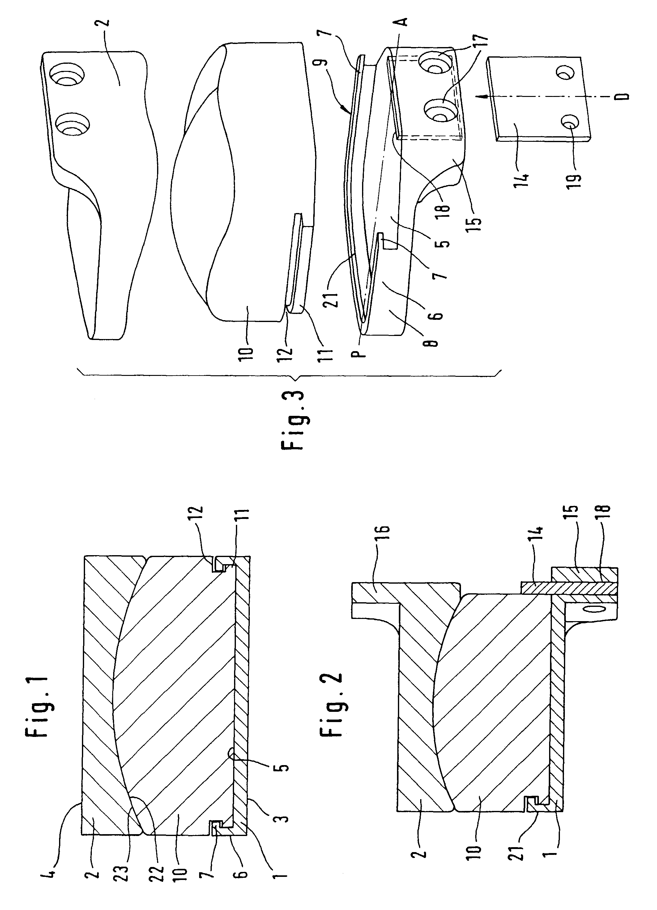
[0029]The lower cover plate 1 and the upper cover plate 2 of the first embodiment have outer surfaces 3 and 4, respectively, which are intended for anchoring to the associated vertebral body. They are preferably plane. However, other substantially flat configurations including suitable surface structures for better anchoring to the bone are also conceivable. The cover plates are preferably made of metal.

[0030]The lower cover plate 1 has a plane bottom surface 5 facing toward the upper cover plate 2 and enclosed on three sides by a collar 6 which, above an inner undercut, forms an inwardly projecting ridge 7. The lower cover plate 1 is of oval or approximately rectangular shape in plan view.

[0031]The bottom surface 5 and the collar 6 of the lower cover plate 1 form a seat for the prosthesis core 10, which is made of a material with good sliding properties, for example polyethylene. It has a plane lower surface which matches the bottom surface 5 and which is delimited laterally and do...

third embodiment

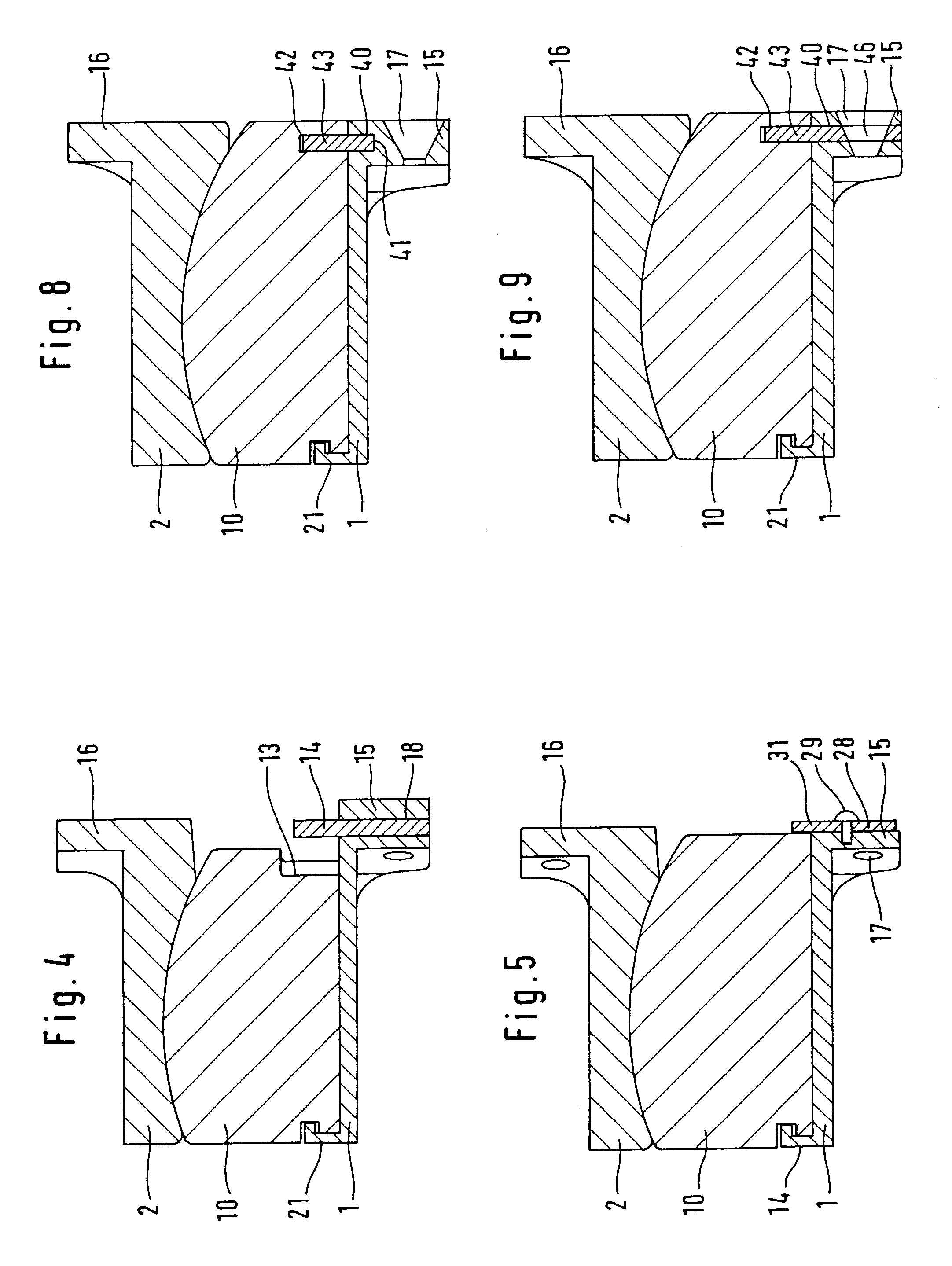
[0042]For the third embodiment according to FIGS. 8 through 12, the above description of FIGS. 1 through 3 also applies, except for the ventral limit-stop device.

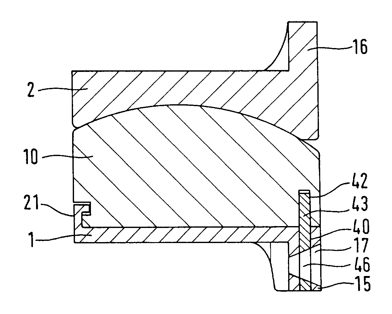
[0043]A slot 40, cut-in along the ventral edge of the lower cover plate 1, extends fully from top to bottom in the left half of the flange 15 in FIG. 10 and, in the right part of the flange 15, is delimited by the broken line 41 shown in FIG. 10. Opposite the slot 40, a slot 42 is cut into the underside of the prosthesis core 10 and lies flush with the slot 40. The two slots 40, 42 serve to receive a limit-stop plate 43 whose contour approximately matches the limits of the space which is intended to receive it and which is formed by the slots 40, 42. As FIG. 10 shows, it can be pushed into the slots 40, 42 from the side after the prosthesis core 10 has been inserted.

[0044]The limit-stop plate 43 can be provided at the end with a lug 44 which, after complete insertion of the limit-stop plate 43 into the slots 40, 42, protrud...


PUM


Abstract

An intervertebral prosthesis, in particular for the cervical spine, includes a first cover plate to be connected to a first vertebral body, a second cover plate to be connected to the second vertebral body, and a prosthesis core which forms an articulation with the second cover plate. The prosthesis core is held by a seat of the first cover plate which is designed as a guide device. The core can be pushed into the guide device from the ventral side in the anterior-posterior (AP) direction relative to the first cover plate. A limit-stop plate is provided on the ventral edge of the first cover plate. This limit-stop plate is displaceable in a slide guide between a locking position and a nonlocking position.

Description

FIELD AND BACKGROUND OF THE INVENTION[0001]Intervertebral prostheses are used for replacing intervertebral disks. They comprise two cover plates whose outer surfaces are designed for connection to adjacent vertebral bodies, and of an articulation device enclosed by the cover plates. In a known prosthesis type (WO 01 / 01893, FR-A-2718635), the upper cover plate forms a concavely spherical articulation surface on its inner side, which cooperates with the convexly spherical top surface of a prosthesis core of polyethylene in order to form an articulation. The flat underside and the edge of the core are received with matching fit in a seat which is formed by the lower cover plate. This seat comprises a plane bottom surface and a vertical edge which surrounds the latter on three sides (laterally and dorsally). On the sides, the edge is formed by two undercut edge ridges which extend substantially in the anterior-posterior (hereinafter “AP”) direction and to which complementary projecting ...

Claims


Application Information

Patent Timeline
Patent Type & Authority Patents(United States)
IPC IPC(8): A61F2/44A61F2/00A61F2/30
CPCA61F2/4425A61F2002/30387A61F2002/30392A61F2002/30397A61F2002/304A61F2002/30517A61F2310/00011A61F2002/30616A61F2002/30649A61F2002/3065A61F2002/443A61F2220/0025A61F2002/30578
Inventor KELLER, ARNOLDMCAFEE, PAUL C.
Owner CERVITECH INC
Why Eureka
Try Eureka