Compression molding method and mold clamping apparatus

a clamping apparatus and compression molding technology, applied in auxillary shaping apparatus, manufacturing tools, applications, etc., can solve the problems of difficult to achieve consistent clamping pressure, difficult to precisely control the mold, and reduced molding dimensional accuracy and molding defects, etc., to achieve stable injection press molding, small fluctuations, and high degree of precision

Active Publication Date: 2006-02-21
MEIKI
View PDF7 Cites 15 Cited by
  • Summary
  • Abstract
  • Description
  • Claims
  • Application Information

AI Technical Summary

Benefits of technology

[0021](6) A compression molding method according to any one of the above-indicated mode (4) or (5), wherein when calculating the third control signal in the initial stage of the mold clamping operation, the final target position is set to a position on a negative side, where a completely closed state of the stationary mold half and the movable mold half is designated as zero position and a mold parting direction is designated as a positive side. According to this mode, the final target position can be located at a position that none of the mold clamping mechanisms can reach in the initial stage of the mold clamping operation, whereby deviation between the final target position and the average value of sensed positions can be obtained consistently. As a result, the mold clamping operation in the initial stage, controlled with reference to this deviation, can be made stable.
[0022](7) A compression molding method according to any one of the above-indicated modes (1)–(6), wherein the compression molding comprises an injection press molding, and the injection press molding is executed by injecting molten resin material to fill the mold cavity defined by the stationary mold half and the movable mold half in a state of being parted by a predetermined amount, and then implementing the mold clamping operation. In order to ensure stable injection press molding, this mode allows a target level of mold clamping force to be consistently exerted on all molding compound filling the mold cavity, while minimizing an amount of tilt of the stationary mold half and movable mold half relative to each other. Thus, it is possible to consistently mold a desired molding with a high degree of precision.
[0023](8) A compression molding method according to the above-indicated modes (3), wherein the step of obtaining the clamping control signal by adding the first control signal and the second control signal, further includes the steps of: setting the first control signal to 0 and obtaining the clamping control signal on the basis of the second control signal in the event that the average value of the sensed pressures in the mold clamping hydraulic cylinder mechanisms or the sensed pressure in any of the plurality of mold clamping hydraulic cylinder mechanisms lies in a preset blind area. According to this mode, small fluctuations and oscillations in the clamping control signal used in the mold clamping operation can be eliminated or minimized, thus achieving a stabilized mold clamping operation. Therefore, even where the target mold clamping force for mold clamping is switched in the course of the mold clamping operation, for example, unintentional and unwanted fluctuations in mold clamping pressure can be effectively avoided.
[0024](9) A compression molding method according to the above-indicated mode (3) or (8), further comprising the steps of: sensing pressure in the plurality of mold clamping hydraulic cylinder mechanisms in the event of a pressure release to reduce pressure in the plurality of mold clamping hydraulic cylinder mechanisms after completing the mold clamping operation; calculating an average value of the pressure obtained; calculating a fourth control signal on the basis of deviation between a preset target value for pressure release and the average value of the pressure obtained; and obtaining the clamping control signal by adding the second control signal and the fourth control signal. According to this mode, even during the pressure release operation occurring after the compression molding operation using a predetermined mold clamping force, the mold clamping pressure can be reduced in a stable manner while eliminating or reducing tilt of the stationary mold half and the movable mold half relative to each other. This makes it possible to further improve quality consistency of moldings.
[0025](10) A mold clamping apparatus comprising: (a) a stationary mold half and a movable mold half which cooperate to define therebetween a mold cavity; (b) a plurality of mold clamping mechanisms adapted to exert a mold clamping force across the stationary plate and the movable plate to bring about a mold clamping operation from a state of the stationary and movable mold halves being parted by a predetermined amount with molten resin material present in the mold cavity in order to effect a compression molding; (c) pressure sensors for sensing mold clamping forces in the plurality of mold clamping mechanisms to obtain sensed mold clamping forces; (d) a target mold clamping force setting member for presetting a target mold clamping force for mold clamping; (e) a first computing member for obtaining a first control signal on the basis of deviation between an average value of the sensed mold clamping forces in the plurality of mold clamping mechanisms and the target mold clamping force for mold clamping set by the target mold clamping force setting member; (f) position sensors for sensing positions of movable members of the plurality of mold clamping mechanisms to obtain sensed positions of the movable member; (g) a target position setting member for calculating an average value of the positions of the movable members in the plurality of mold clamping mechanisms, and setting the average value as a successive target position; (h) a second computing member for calculating a second control signal on the basis of deviation between each of the sensed positions of the movable members of the plurality of mold clamping mechanisms and the successive target position; and (i) a clamping control signal computing member for adding the first control signal and the second control signal and calculating a clamping control signal for each of the mold clamping mechanisms.
[0026]The mold clamping apparatus having structure according to the present invention is capable of advantageously implementing the aforementioned compression molding method according to the invention.

Problems solved by technology

When carrying out compression molding, factors, such as symmetricity of the mold cavity or bias of the gate location prone to causes the molding compounds filled within the cavity to create reaction force to a mold clamping force or a non-uniform pressure distribution within the cavity, when the stationary and movable mold haves are clamped together.
As a result, the stationary and movable mold halves tilt relative to each other so that the two mold halves cannot be clamped in parallel, possibly leading to reduced dimensional accuracy and molding defects of moldings.
However, the control method according to the former (JP-A-5-269750) has some drawbacks, since mold clamping is controlled simply on the basis of the stroke position in each mold clamping hydraulic cylinder mechanism.
This makes it difficult to precisely control the mold clamping hydraulic cylinder mechanism at around completion of clamping or during a pressure release operation, for example, resulting in the problem of difficulty in achieving consistent clamping pressure and a tendency for clamping pressure to fluctuate during the mold clamping operation.
With the control device according to the latter (JP-A-11-179770), there is an unavoidable delay between operation of the one mold clamping hydraulic cylinder mechanism and of the other mold clamping hydraulic cylinder mechanisms which follow it, resulting in a tendency for the stationary and movable mold halves to tilt relative to each other.
Additionally, clamping pressure is controlled solely on the basis of detected pressure of the one mold clamping hydraulic cylinder mechanism, making it difficult to ascertain clamping pressure acting on the molding overall.

Method used


Image

  • Compression molding method and mold clamping apparatus
  • Compression molding method and mold clamping apparatus
  • Compression molding method and mold clamping apparatus

Examples


Embodiment Construction

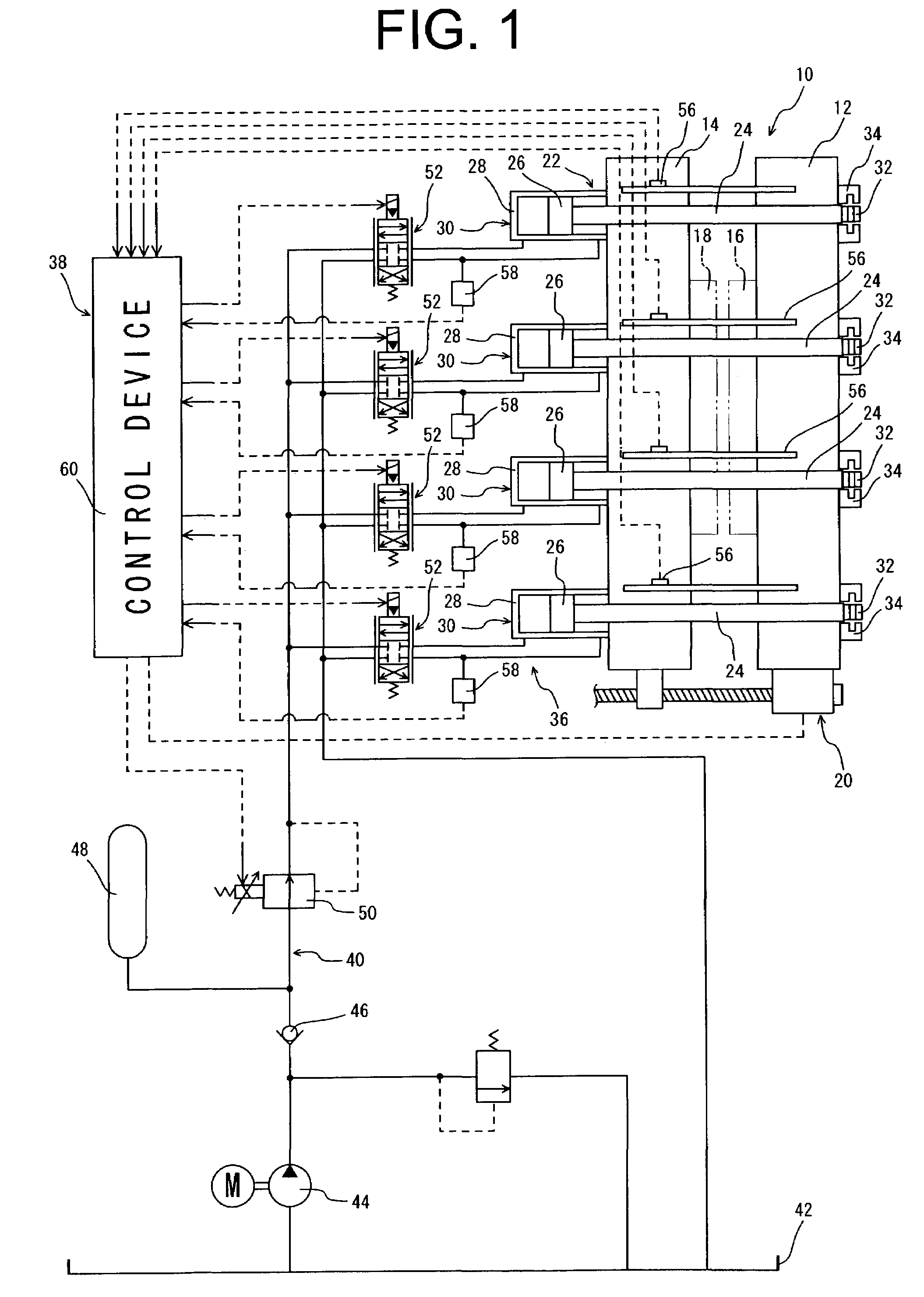
[0039]Referring first to FIG. 1, there is shown a schematic diagram of a mold clamping apparatus 10 constructed according to one preferred embodiment of the invention, which is suitable for implementing a compression molding method according to the invention. This mold clamping apparatus 10 comprises a stationary plate 12 fixedly supported by means of an apparatus base (not shown) and a movable plate 14 positioned opposed to this stationary plate 12, with the movable plate 14 capable of relative displacement towards and away from the stationary plate 12. A stationary mold half 16 and a movable mold half 18, which cooperate to constitute a mold, are respectively attached to opposed faces of the stationary and movable plates 12, 14. This movable plate 14 is moved toward and away from the stationary plate 12 so that the stationary and movable mold halves 16, 18 are caused to undergo a mold closing or mold parting operation to be placed in a mold closing position or mold parting positio...


PUM

PropertyMeasurementUnit
clamping forceaaaaaaaaaa
mold clamping forcesaaaaaaaaaa
mold clamping forceaaaaaaaaaa

Abstract

Disclosed is a compression molding method comprising the steps of: calculating an average value of mold clamping forces sensed in a plurality of mold clamping mechanisms for clamping a stationary and a movable mold half; obtaining a first control signal on the basis of deviation between a preset target mold clamping force and an average value of sensed mold clamping forces; sensing positions of movable members of the mold clamping mechanisms; obtaining an average value of sensed positions; setting the average value as a successive target position; obtaining a second control signal on the basis of deviation between each of the sensed positions and the successive target position; and obtaining a clamping control signal for each of the clamping mechanisms by adding the first control signal and the second control signal. An apparatus suitable for implementing the method is also disclosed.

Description

[0001]The disclosure of Japanese Patent Application No. 2002-173820 filed on Jun. 14, 2002 including the specification, drawings and abstract is incorporated herein by reference in its entirety.BACKGROUND OF THE INVENTION[0002]1. Field of the Invention[0003]The present invention relates to a compression molding method and mold clamping apparatus that may be suitable for use in injection compression molding, injection press molding, and pressurized press molding of synthetic resin materials and other molding compounds.[0004]2. Description of the Related Art[0005]A compression molding is known as one type of molding methods for molding compounds such as plasticized synthetic resin materials. The known compression molding involves the steps of: parting by a given amount a stationary mold half and a movable mold half that cooperate to provide a mold having a mold cavity defined therebetween, while introducing the molding compound into the mold cavity; and clamping the mold in this state...

Claims


Application Information

Patent Timeline
Patent Type & Authority Patents(United States)
IPC IPC(8): B29C45/64B29C43/58B29C45/56B29C45/70B29C45/76B29C45/80
CPCB29C43/58B29C45/7653B29C45/80B29C2945/76869B29C2043/5808B29C2043/5833B29C2945/76006B29C2945/76083B29C2945/7623B29C2945/76498B29C2945/76505B29C2945/76568B29C2945/76702B29C2945/76785B29C45/561
Inventor OKADO, SHOJIYABUKI, YASUHIRO
Owner MEIKI
Why Eureka
Try Eureka