Brushless motor

a brushless, motor technology, applied in the direction of mechanical equipment, magnetic circuit rotating parts, magnetic circuit shape/form/construction, etc., can solve the problems of lubricating oil leakage, unavoidable gap between the configuration on the bearing side and the configuration on the rotor side, etc., to prevent the scattering of rotors, simple press processing, and simple and inexpensive production of motors

Inactive Publication Date: 2006-02-21
TOKYO PARTS IND CO LTD
View PDF5 Cites 10 Cited by
  • Summary
  • Abstract
  • Description
  • Claims
  • Application Information

AI Technical Summary

Benefits of technology

[0020]By disposing a lubricating oil absorption member with its outer periphery in a compressed state between the magnet and rotor case, lubricating oil that would otherwise scatter across the inside of the rotor case is absorbed, and by stopping the lubricating oil with such compressed portion, lubricating o...

Problems solved by technology

However, because a configuration is needed on both the stator side and rotor side in order to constitute these scattering prevention means, a gap is unavoidably provided between the configuration on the bearing side and the configuration on the rotor side.
In such cases, if these motors are attached to devices in which they a...

Method used


Image

  • Brushless motor
  • Brushless motor
  • Brushless motor

Examples


Embodiment Construction

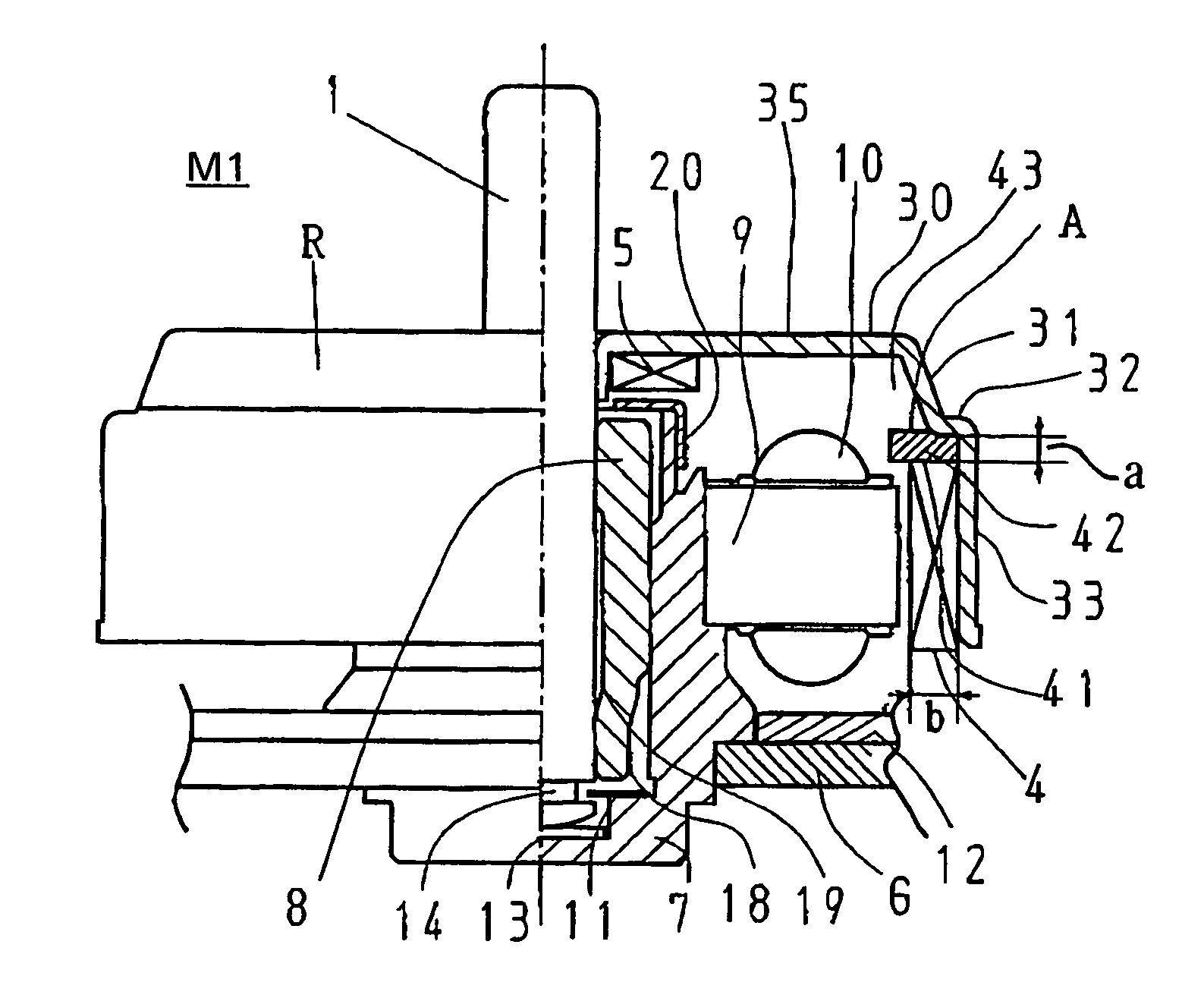
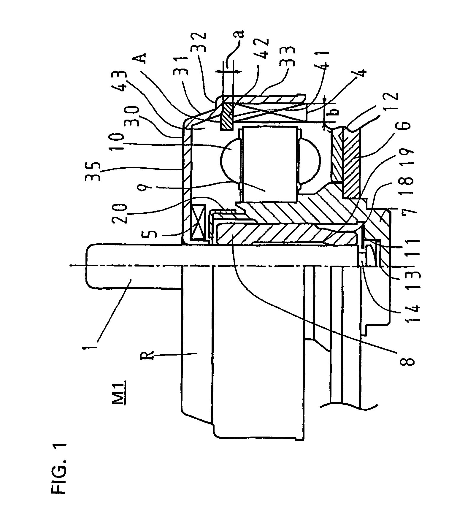
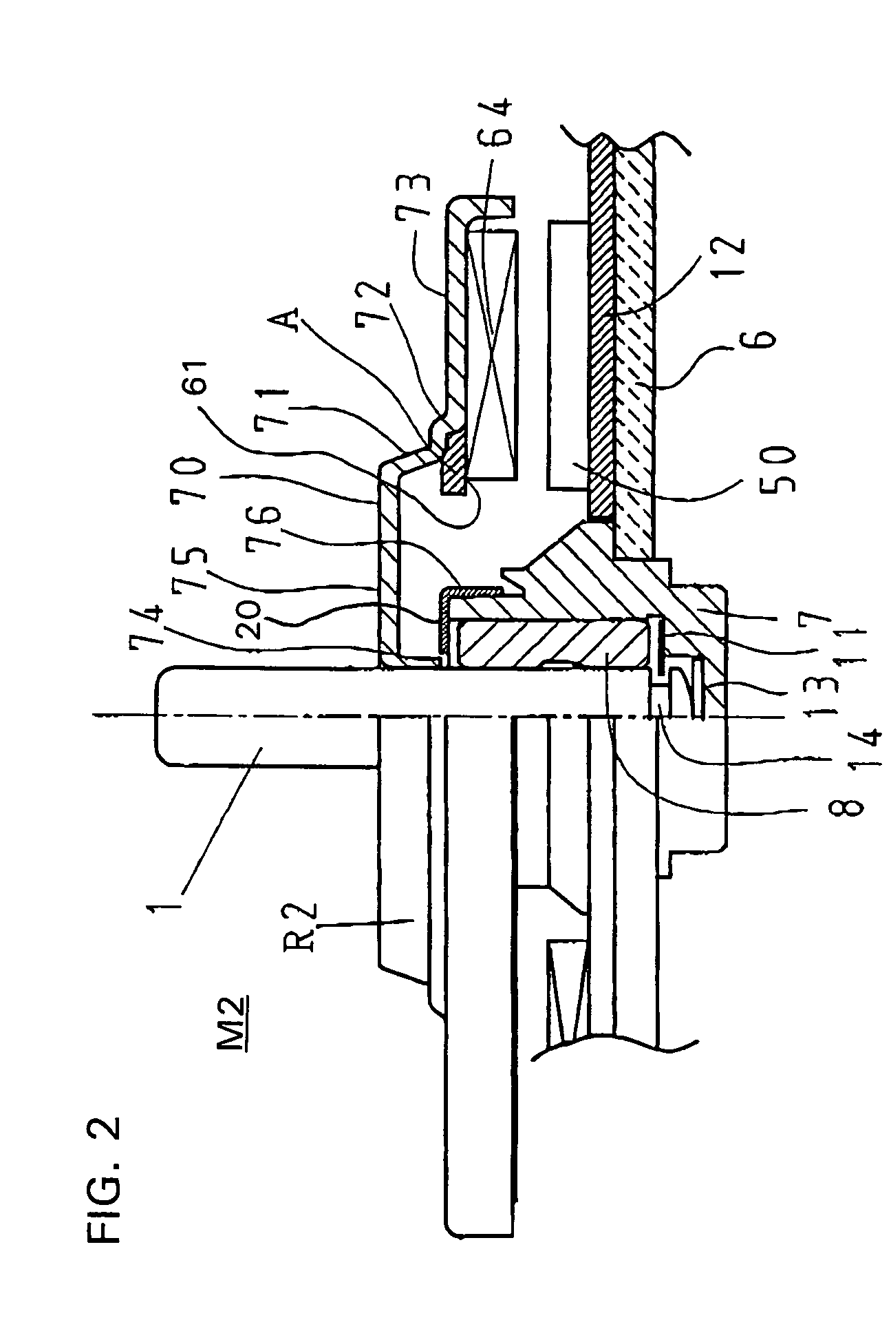
[0026]Embodiments of the invention will be explained with reference to the drawings. Elements that are the same as those in the conventional motor and have the same operation and effect have been given the same number, and an explanation thereof has been omitted.

[0027]Unless otherwise specified, the configuration is formed in a circular shape centering on the rotary shaft 1.

[0028]The stator of this motor M1 comprises a stator base 6 to which a bearing holder 7 is fixed by caulking or the like, a stator core 9 fixed on the bearing holder 7, a coil 10 wrapped around the stator core 10, and a flexible base 12 provided on the upper surface of the stator base 6.

[0029]On the inside of the bearing holder 7, a thrust-receiving part 13, a slip-off prevention washer 11 and a bearing 8 are attached, and on the upper end thereof an attraction plate 20 is attached. A rotor case 30 is fixed to the rotary shaft 1.

[0030]The rotor case 30 is made of magnetic plate material, and is formed through pre...


PUM


Abstract

A lubricating oil scattering prevention arrangement provided near a bearing whereby the outward scattering of lubricating oil that leaked from between a stator and rotor due to tilting, impact or the like is prevented. A plate-shaped rotor case 30 is provided with a descending portion 31, a step portion 32 and an outer peripheral portion 33. A magnet 4 is provided on the inner side of the outer peripheral portion 33 and a lubricating oil absorption member is provided between the magnet 4 and the step portion 32. Because an outer peripheral portion of the lubricating oil absorption member is compressed by the magnet 4 upper surface portion and the step portion 32 and thus attached, the lubricating oil absorption member absorbs lubricating oil leaked from the bearing part and the compressed portion prevents the lubricating oil from leaking outwardly.

Description

BACKGROUND OF THE INVENTION[0001]1. Field of the Invention[0002]The present invention relates to a brushless motor used in a spindle motor or fan motor in which a disk is driven by a disk drive. More specifically, it relates to a brushless motor provided with an oil-leak prevention means for preventing lubricating oil used in a bearing part thereof from leaking to the outside of the motor.[0003]2. Background Art[0004]A variety of configurations have been used heretofore for brushless motors used in disk drives and the like. FIG. 3 shows such a motor of a relatively low price. In the portion of FIG. 3 to the right of the central line, a cross-sectional view of elements are indicated by shading.[0005]The legend 2 designates a rotor that rotates with a rotary shaft 1. This rotor 2 includes a cylindrical cap-shaped rotor case 3, a magnet 4 attached to the entire periphery of the rotor case 3, and an attraction magnet 5 that impels the rotor 2 in the downward direction in the figure.[000...

Claims


Application Information

Patent Timeline
IPC IPC(8): H02K5/10F16N7/12F16N31/00H02K1/27H02K7/08H02K7/09H02K21/22H02K21/24
CPCF16N31/00H02K7/09H02K7/085F16N7/12H02K1/2786H02K1/2791
Inventor TSUCHIYA, MASAHISA
Owner TOKYO PARTS IND CO LTD
Why Eureka
Try Eureka