Optical see-through augmented reality modified-scale display

a technology of augmented reality and optical display, applied in the field of optical display and sensing, can solve the problems of limiting the resolution of what the user can see, affecting the accuracy of the display, and the delay between real and virtual views is difficult to match, so as to achieve the effect of increasing accuracy and increasing accuracy

Inactive Publication Date: 2006-02-21
HRL LAB
View PDF116 Cites 255 Cited by
  • Summary
  • Abstract
  • Description
  • Claims
  • Application Information

AI Technical Summary

Benefits of technology

[0027]In yet another aspect, or aspect, of the present invention, the step of measuring precisely the user's current orientation by a sensor suite further includes measuring the user's orientation using a video camera and a video feature recognition and tracking movement module. The video feature recognition and tracking movement module receives a sensor suite video camera output from a sensor suite video camera and provides the sensor fusion module measurements to enable the sensor fusion module to produce t

Problems solved by technology

Both streams have inherent delays in the tens of milliseconds.
2) Resolution: Video blending limits the resolution of what the user sees, both real and virtual, to the resolution of the display devices, while optical blending does not reduce the resolution of the real world.
On the other hand, an optical approach has the following disadvantages with respect to a video approach: 1) Real and virtual view delays are difficult to match.
The optical approach offers an almost instantaneous view of the real world, but the view of the virtual is delayed.
Currently, optical approaches do not have this additional registration strategy available to them.
Most display devices cannot come close to this level of contrast.
The resolution of video sensing and video display elements is limited, as is the contrast and brightness.
One of the most basic problems lim

Method used


Image

  • Optical see-through augmented reality modified-scale display
  • Optical see-through augmented reality modified-scale display
  • Optical see-through augmented reality modified-scale display

Examples


Embodiment Construction

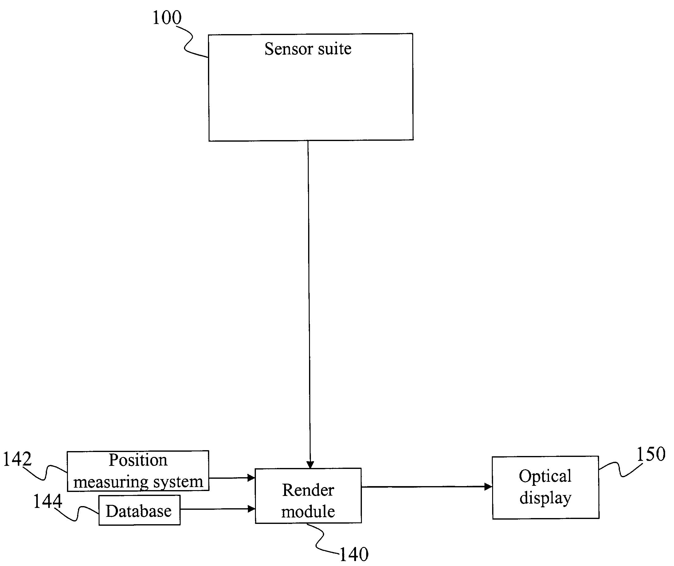
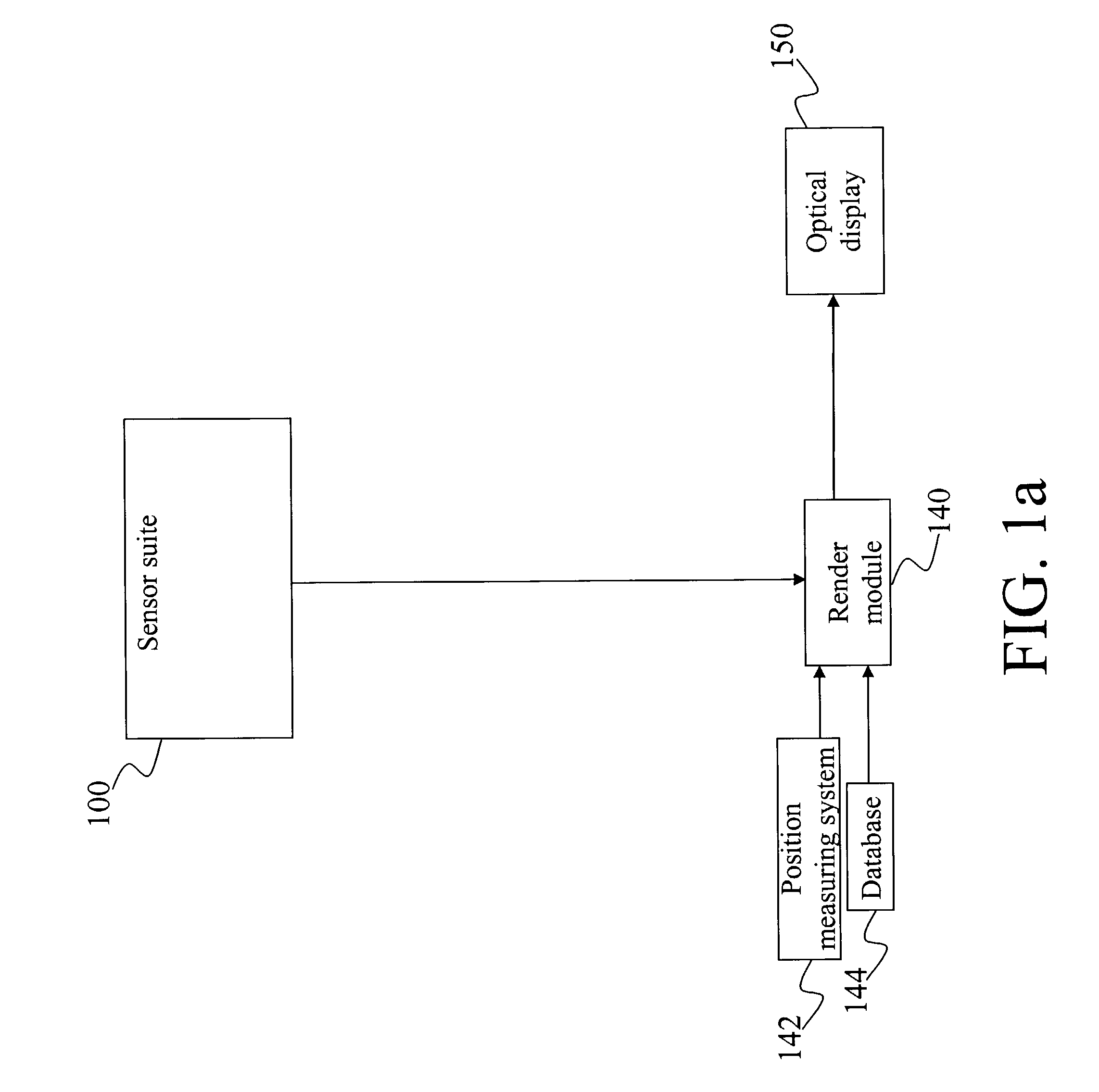
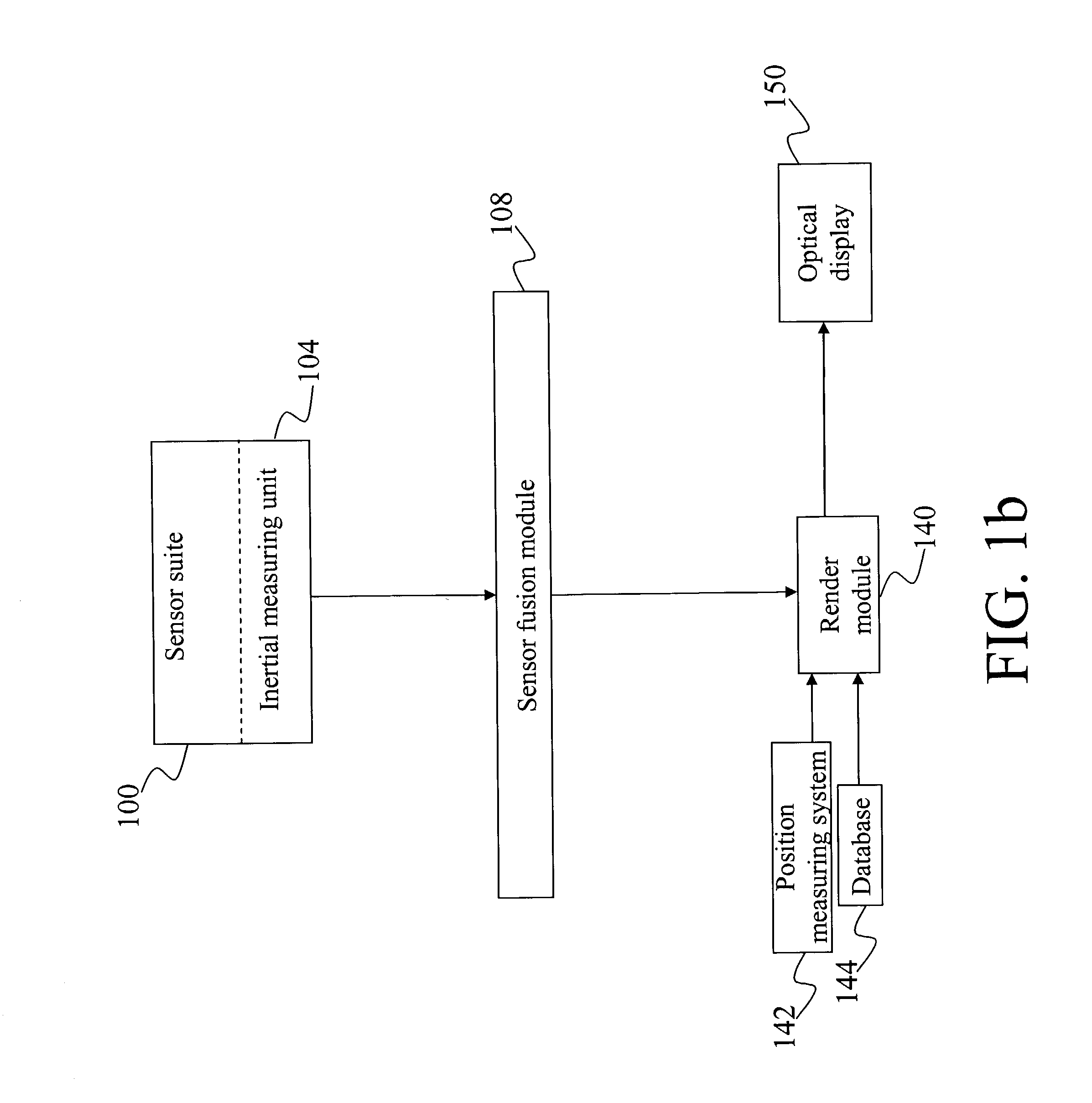
[0056]The present invention relates to the field of Augmented Reality (AR). More specifically, this invention presents a method and apparatus for using an optical display and sensing technologies to superimpose, in real time, graphical information upon a user's magnified view of the real world, and may be tailored to a variety of applications. The following description is presented to enable one of ordinary skill in the art to make and use the invention and to incorporate it in the context of particular applications. Various modifications, as well as a variety of uses in different applications will be readily apparent to those skilled in the art, and the general principles defined herein may be applied to a wide range of aspects. Thus, the present invention is not intended to be limited to the aspects presented, but is to be accorded the widest scope consistent with the principles and novel features disclosed herein.

[0057]The present invention is useful for providing an optical see-...


PUM


Abstract

A method and system for providing an optical see-through Augmented Reality modified-scale display. This aspect includes a sensor suite 100 which includes a compass 102, an inertial measuring unit 104, and a video camera 106 for precise measurement of a user's current orientation and angular rotation rate. A sensor fusion module 108 may be included to produce a unified estimate of the user's angular rotation rate and current orientation to be provided to an orientation and rate estimate module 120. The orientation and rate estimate module 120 operates in a static or dynamic (prediction) mode. A render module 140 receives an orientation; and the render module 140 uses the orientation, a position from a position measuring system 142, and data from a database 144 to render graphic images of an object in their correct orientations and positions in an optical display 150.

Description

STATEMENT OF GOVERNMENT RIGHTS[0001]This invention is used in conjunction with DARPA ITO contracts #N00019-97-C-2013, “GRIDS”, and #N00019-99-2-1616, “Direct Visualization of the Electronic Battlefield”, and the U.S. Government may have certain rights in this invention.TECHNICAL FIELD[0002]The present invention is related to the field of Augmented Reality (AR). More specifically, this invention presents a method and an apparatus for using an optical display and sensing technologies to superimpose, in real time, graphical information upon a user's magnified view of the real world.BACKGROUND[0003]Augmented Reality (AR) enhances a user's perception of, and interaction with, the real world. Virtual objects are used to display information that the user cannot directly detect with the user's senses. The information conveyed by the virtual objects helps a user perform real-world tasks. Many prototype AR systems have been built in the past, typically taking one of two forms. In one form, th...

Claims


Application Information

Patent Timeline
IPC IPC(8): G09G5/08G03B13/28G06F3/00G06F3/01
CPCG03B13/28G06T19/006G06F3/011
Inventor AZUMA, RONALD T.SARFATY, RON
Owner HRL LAB
Why Eureka
Try Eureka