Disk-shaped storage medium and tracking method using the same

a technology of disk-shaped storage media and tracking method, which is applied in the direction of digital signal error detection/correction, instruments, recording signal processing, etc., can solve the problems of reducing the area required for the address data portion, reducing the data recording area, and reducing the reliability of the disk, so as to reduce the redundancy of the address part, stable tracking pull-in operation, and the effect of reducing the pitch

Inactive Publication Date: 2006-02-21
PANASONIC CORP
View PDF25 Cites 3 Cited by
  • Summary
  • Abstract
  • Description
  • Claims
  • Application Information

AI Technical Summary

Benefits of technology

[0026]According to the above-mentioned configuration and methods, in order to identify the starting position of the address, it is not required to modulate the address data portion and to use a unique pattern obtained by the modulation rules as address marks. Therefore, the redundancy of the address part can be reduced considerably, thus achieving a high-density optical disk.
[0027]In the optical disk of the present invention, the positions where the tracking polarities are switched can be detected before a tracking pull-in operation. Therefore, in an optical disk with a track pitch providing a high-density track, a stable tracking pull-in operation can be performed.
[0028]Furthermore, the tracking control performed according to the signals from the wobble pits while recording and reproduction are performed only in groove portions enables the track pitch to be reduced and the difference in the recording / reproduction characteristics between tracks to be eliminated simultaneously.

Problems solved by technology

Therefore, there has been a problem that the area required for the address data portion increases and thus the data recording area is reduced.
Furthermore, in the case of using one bit of the polarity inversion detection pit, it has been difficult to secure sufficient reliability with respect to defects of the disk and damages on the disk surface.

Method used


Image

  • Disk-shaped storage medium and tracking method using the same
  • Disk-shaped storage medium and tracking method using the same
  • Disk-shaped storage medium and tracking method using the same

Examples


first embodiment

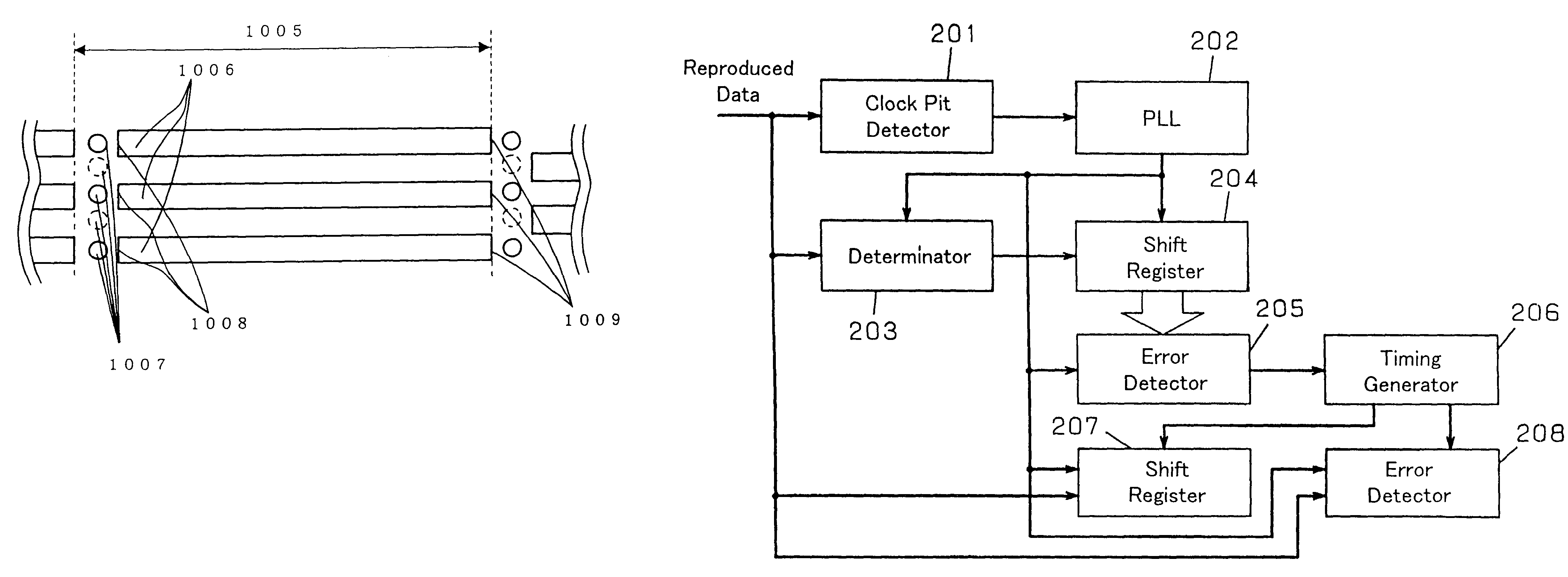
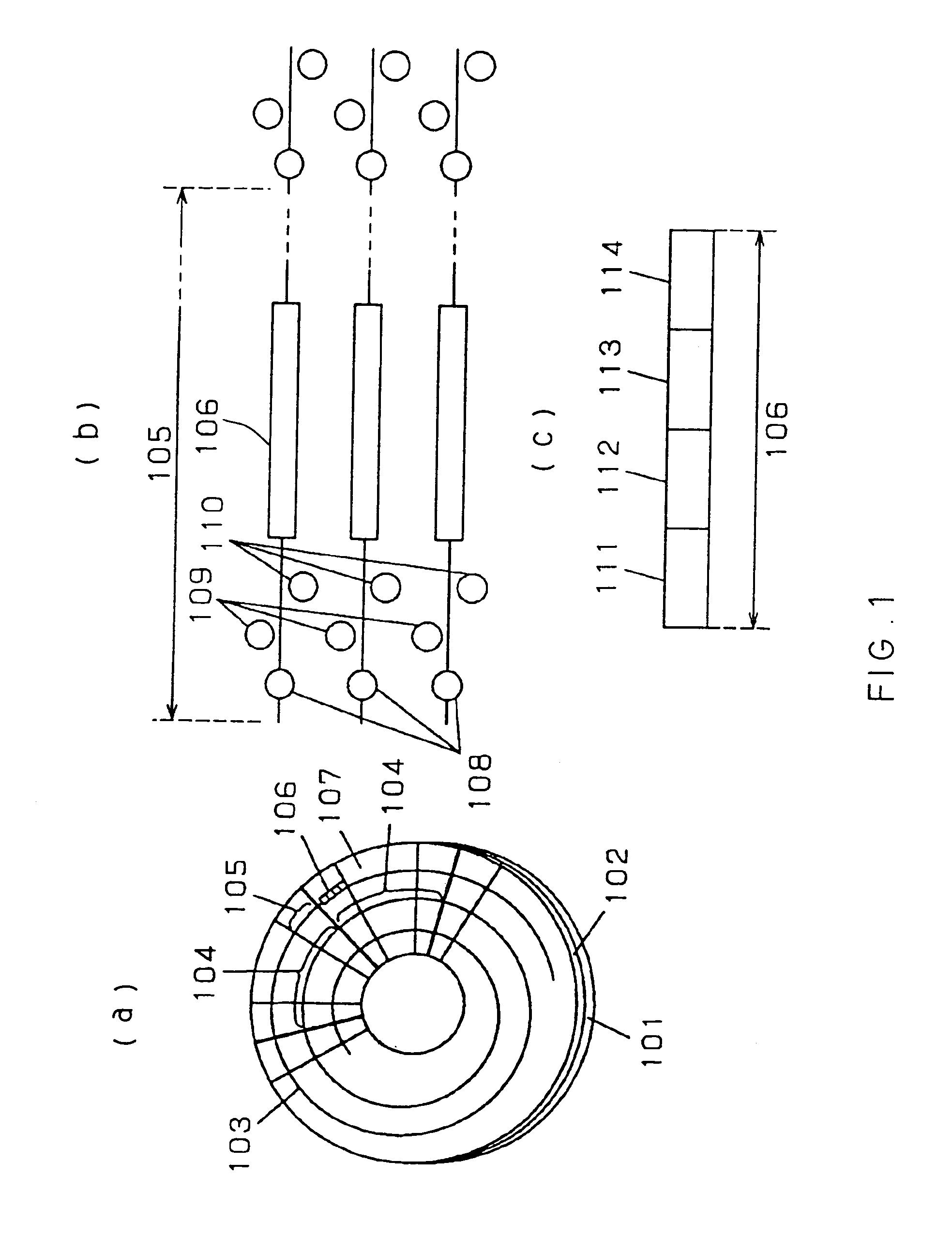
[0043]FIGS. 1(a), 1(b), and 1(c) show a general structural drawing, a drawing of a segment structure, and a drawing illustrating an address area, respectively, of an optical disk according to a first embodiment of the present invention.

[0044]In FIG. 1(a), numeral 101 indicates a substrate, numeral 102 a recording film, numeral 103 a track, numeral 104 a sector of a divided portion of the track, numeral 105 a segment of a divided portion of the sector, numeral 106 an address for identifying the sector, and numeral 107 a data recording area for recording data. The track 103 is divided into 32 sectors 104 around the disk. Further, the sector 104 is divided into 40 segments 105, and the address 106 is recorded in the first segment.

[0045]As shown in FIG. 1(b), in the leading location of the segment 105, a clock pit 108 for generating a clock and wobble pits 109 and 110 used for obtaining a tracking signal are provided. A tracking system in the present embodiment is a sample servo system ...

second embodiment

[0053]FIGS. 5(a), 5(b), and 5(c) show a general structure, a segment structure, and an address area, respectively, of an optical disk according to a second embodiment of the present invention.

[0054]In FIG. 5(a), numeral 501 denotes a substrate, numeral 502 a recording film, numeral 503 a first track, numeral 504 a second track, numeral 505 a sector of a divided portion of the track, numeral 506 a segment of a divided portion of the sector, numeral 507 an address for identifying the sector, and numeral 508 a data recording area for recording data. The first track 503 and the second track 504 are divided into 32 sectors 505 around the disk. The sector 505 further is divided into 40 segments 506. The address 507 is recorded in the first segment. The other second to fortieth segments serve as the data recording area 508.

[0055]As shown in FIG. 5(b), in the leading location of the segment 506, a clock pit 509 for generating a clock and a pair of wobble pits 510 and 511 used for obtaining ...

third embodiment

[0064]FIG. 8(a) and FIG. 8(b) show a general structure and a segment structure, respectively, of an optical disk according to a third embodiment of the present invention.

[0065]In FIG. 8(a), numeral 801 indicates a substrate, numeral 802 a recording film, numeral 803 a first track, numeral 804 a second track, and numeral 805 a segment obtained by dividing the tracks into 1280 segments. As shown in FIG. 8(b), in the leading location of the segment 805, a clock pit 806 for generating a clock, a pair of wobble pits 807 and 808 used for obtaining a tracking signal, and an address pit 809 arranged so that the address data are distributed to be positioned as one bit each. The tracking system in the present embodiment is the single-spiral polarity switching type sample servo system as in the second embodiment.

[0066]In the present embodiment, the address data is decomposed into one-bit data to be arranged in the segments 805, which is an important characteristic. In the first and second embo...


PUM

PropertyMeasurementUnit
areasaaaaaaaaaa
data sizeaaaaaaaaaa
densityaaaaaaaaaa

Abstract

A disk-shaped storage medium allowing the redundancy of an address part to be reduced and data to be recorded with a higher density, and a tracking method using the same are provided. In a disk-shaped storage medium in which a track is divided into a plurality of areas and address data are positioned in the plurality of areas, error detection codes are added to data common to adjacent tracks of the address data for identifying the data common to adjacent tracks. This enables the synchronous process to data in reproducing the address data to be carried out without using a unique synchronization pattern.

Description

[0001]This application is a divisional of application Ser. No. 09 / 647,283, filed Sep. 26, 2000 now U.S. Pat. No. 6,628,578, which is a National Stage Application of PCT / JP00 / 00434 filed Jan. 27, 2000, which application(s) are incorporated herein by reference.TECHNICAL FIELD[0002]The present invention relates to a disk-shaped storage medium on or from which data is recorded or reproduced using a laser beam, and to a tracking method using the disk-shaped storage medium.BACKGROUND ART[0003]Recently, as disk-shaped storage media, optical disks have been put into practical use as large capacity data files and media for storing music or images. However, it further is intended to increase the capacities of such disk-shaped storage media so that they can be applied in more various uses. For efficient access to a large capacity optical disk, the following method is employed in general. That is, recording data are distributed to sectors in a certain unit of data size, and recording and repro...

Claims


Application Information

Patent Timeline
Patent Type & Authority Patents(United States)
IPC IPC(8): G11B5/09G11B7/24G11B7/007G11B7/09G11B20/12G11B20/18G11B27/19G11B27/24G11B27/30
CPCG11B7/00745G11B7/0938G11B20/1217G11B20/1833G11B27/19G11B27/24G11B27/3027G11B7/0901G11B2220/2575G11B2020/1238G11B2020/1267G11B2020/1287G11B2020/1292G11B2220/216G11B2220/2525G11B2220/2529G11B7/007
Inventor NAKAMURA, TADASHIHINO, YASUMORIMIYATAKE, NORIO
Owner PANASONIC CORP
Why Eureka
Try Eureka