High density analog recording using write symbols having distinguishable readout waveforms

a write symbol and high-density technology, applied in the field of optical data storage, can solve the problems of difficult to obtain ideal or near ideal recording marks, lose delicate features in the recorded pattern of information on the media, etc., and achieve the effect of maximizing the use of the available snr and increasing the recording density

Inactive Publication Date: 2006-02-21
AVAGO TECH INT SALES PTE LTD
View PDF13 Cites 3 Cited by
  • Summary
  • Abstract
  • Description
  • Claims
  • Application Information

AI Technical Summary

Benefits of technology

[0007]In one embodiment, it is determined which waveforms the read channel can and should supply given its particular constraints (e.g., spectral content, bandwidth, noise characteristics, restrictions of the peak amplitude, etc.). Once the desired read waveforms have been identified, strategies are developed for recording “patterns” (e.g., amorphous / crystalline regions on phase-change media, magnetic domains on MO media) that can produce the desired waveforms during readout. In one embodiment, a genetic algorithm is used to develop appropriate recording strategies. By employing the heretofore forbidden mark / space patterns at the medium, the proposed analog schemes are capable of delivering higher recording densities. Also, by allowing the system designer to match the read waveforms to channel characteristics, the proposed schemes use the available SNR more efficiently.

Problems solved by technology

It must be recognized, however, that by introducing the techniques of digital recording, delicate features in the recorded patterns of information on the media have been lost.
As higher recording density is required, obtaining ideal or nearly ideal recording marks becomes more difficult.

Method used


Image

  • High density analog recording using write symbols having distinguishable readout waveforms
  • High density analog recording using write symbols having distinguishable readout waveforms
  • High density analog recording using write symbols having distinguishable readout waveforms

Examples


Embodiment Construction

[0029]A detailed description of a preferred embodiment of the invention is provided below. While the invention is described in conjunction with that preferred embodiment, it should be understood that the invention is not limited to any one embodiment. On the contrary, the scope of the invention is limited only by the appended claims and the invention encompasses numerous alternatives, modifications and equivalents. For the purpose of example, numerous specific details are set forth in the following description in order to provide a thorough understanding of the present invention. The present invention may be practiced according to the claims without some or all of these specific details. For the purpose of clarity, technical material that is known in the technical fields related to the invention has not been described in detail so that the present invention is not unnecessarily obscured.

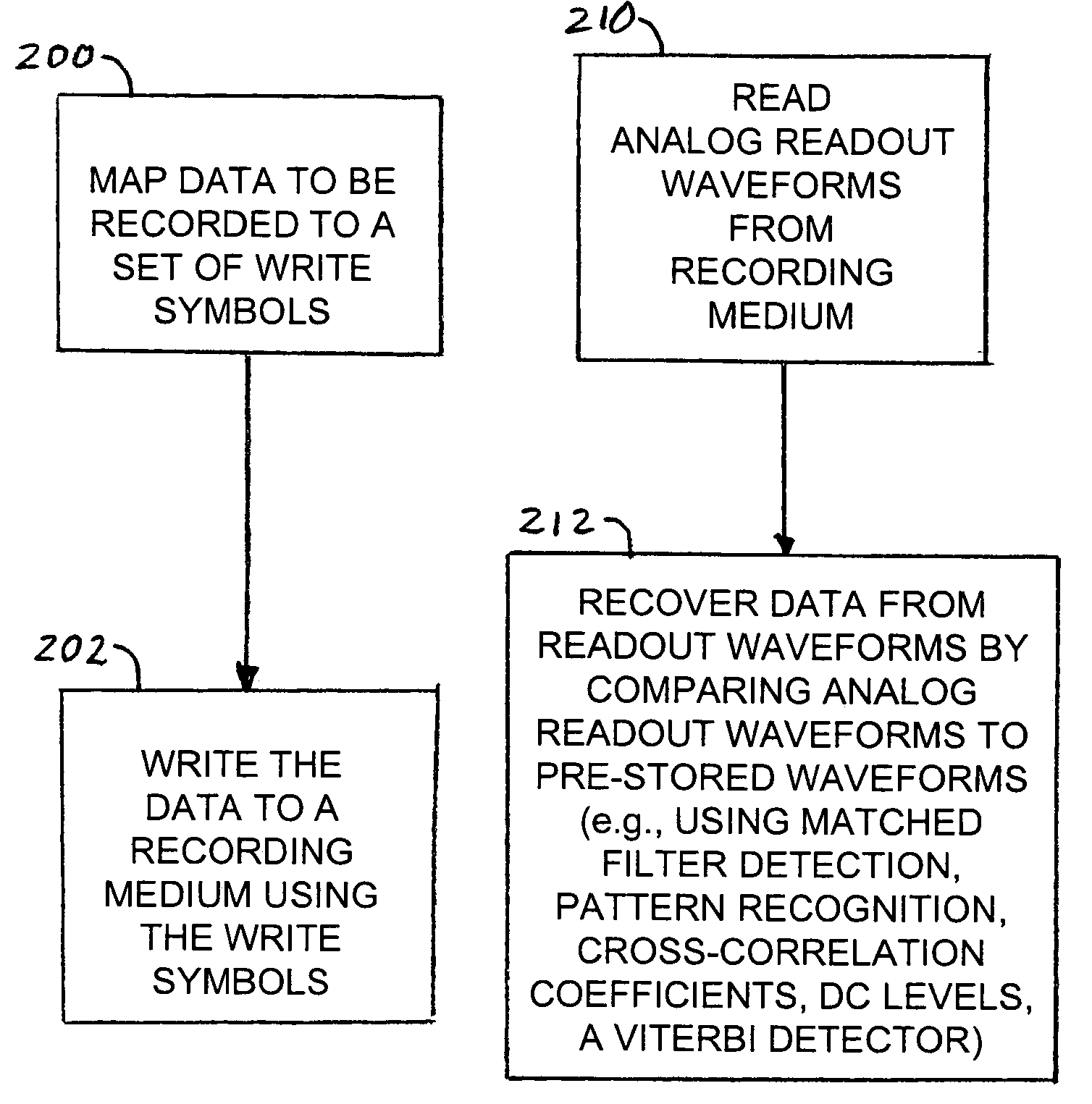
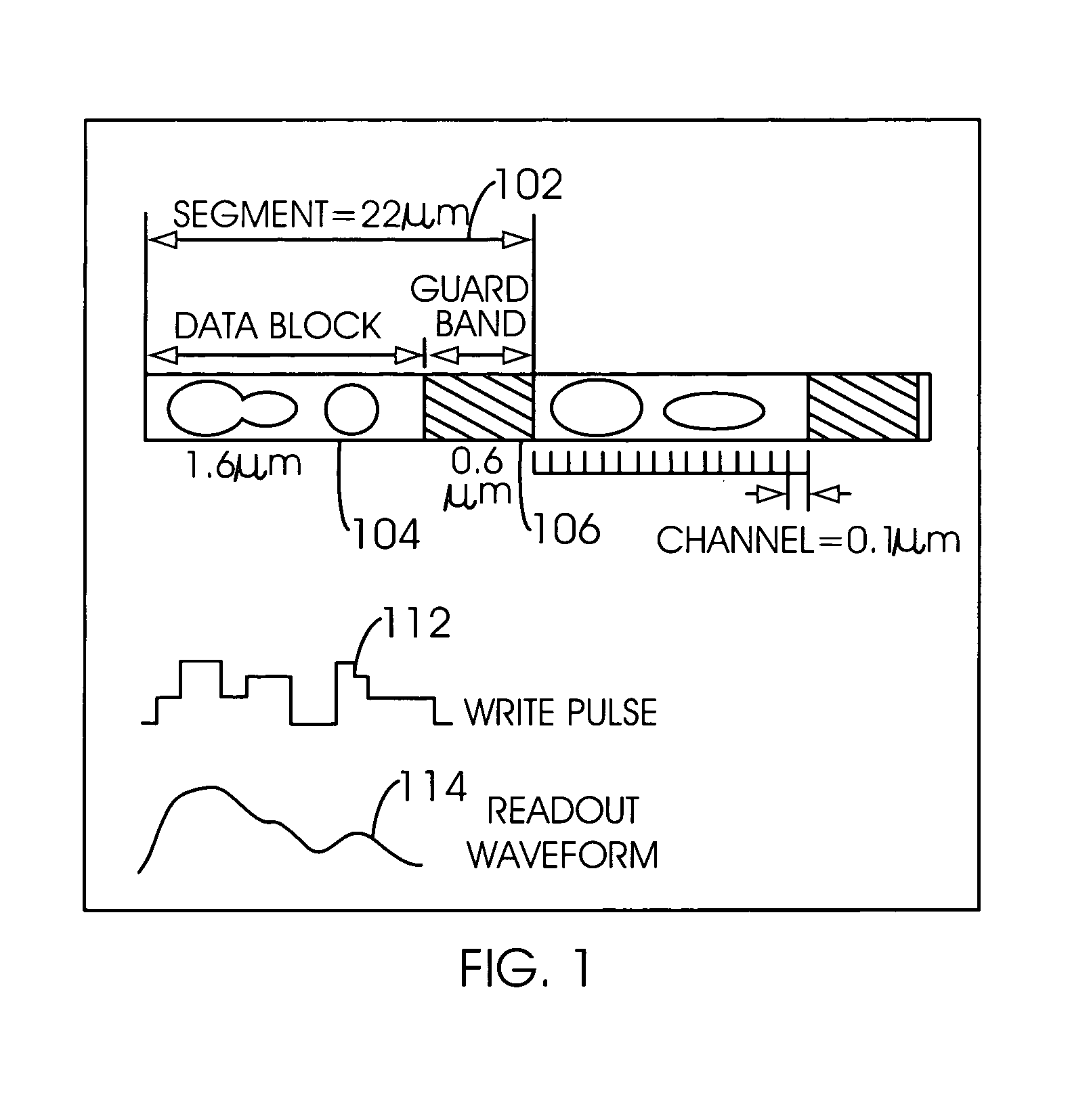
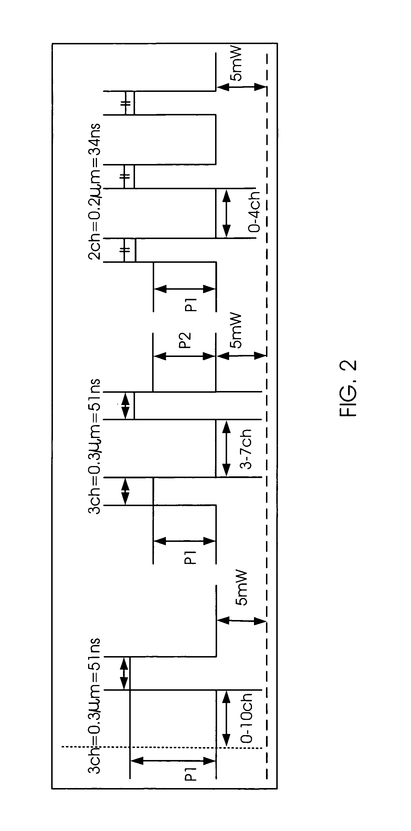
Segmented Recording and Matched-Filter Detection

[0030]In one embodiment, a segmented recording me...


PUM

PropertyMeasurementUnit
segment lengthaaaaaaaaaa
linear track velocityaaaaaaaaaa
thresholdaaaaaaaaaa

Abstract

A method of recording data on a recording medium includes mapping the data to a set of write symbols wherein each write symbol represents more than one bit of the data. The set of write symbols is defined by defining a set of variable write parameters; generating a plurality of candidate write symbols that specify different values for the variable write parameters; generating a plurality of readout waveforms produced by the plurality of candidate write symbols; analyzing the readout waveforms to determine desired set of readout waveforms; and selecting selected ones of the plurality of candidate write symbols that correspond to the desired readout waveforms to be included in the set of write symbols. The data is written to the medium using the write symbols.

Description

CROSS REFERENCE TO RELATED APPLICATIONS[0001]This application claims priority to U.S. Provisional Patent Application No. 60 / 193,059, entitled HIGH DENSITY STORAGE BY SEGMENTED ANALOG RECORDING ON PHASE CHANGE DISK filed Mar. 29, 2000 which is incorporated herein by reference for all purposes and U. S. Provisional Patent Application No. 60 / 244,819, entitled ANALOG RECORDING ON PHASE-CHANGE OPTICAL DISKS filed Oct. 31, 2000 which is incorporated herein by reference for all purposes.[0002]This invention was made with United States Government support by the U.S. Department of Commerce through the NSIC / MORE program under cooperative agreement number 70NANB7H3054. The United States Government has certain rights in this invention.FIELD OF THE INVENTION[0003]The present invention relates generally to optical data storage. More specifically, high density analog recording is disclosed.BACKGROUND OF THE INVENTION[0004]Perhaps the most significant breakthrough in the field of optical data stora...

Claims


Application Information

Patent Timeline
Patent Type & Authority Patents(United States)
IPC IPC(8): G11B7/00G11B7/0045G11B7/006G11B7/007G11B7/013G11B7/125G11B11/105G11B20/02
CPCG11B7/0045G11B7/00454G11B7/0062G11B7/007G11B20/02G11B7/1267G11B7/24088G11B7/013G11B11/10595
Inventor MIYAGAWA, NAOYASUMANSURIPUR, MASUD
Owner AVAGO TECH INT SALES PTE LTD
Why Eureka
Try Eureka