
Method and apparatus for x-ray anode with increased coverage

a technology of x-ray anode and increased coverage, applied in the field of x-ray tubes, can solve the problems of compromising image quality and too large focal spo

Inactive Publication Date: 2006-02-21
GE MEDICAL SYST GLOBAL TECH CO LLC
View PDF5 Cites 39 Cited by
  • Summary
  • Abstract
  • Description
  • Claims
  • Application Information

AI Technical Summary

Benefits of technology

"The present invention is an x-ray tube with two targets that rotate together. The targets have separate cathodes that can be operated simultaneously or independently. The x-ray coverage at the detector can be as high as 120 mm when the cathodes are operated simultaneously. The technical effect of this invention is to provide a more efficient and effective x-ray tube for CT applications."

Problems solved by technology

Further, the focal spot is too big.
While the width is larger than conventional beam widths, which are typically on the order of 60 mm, the quality of the image becomes compromised due to distortion of the image.

Method used


Image

  • Method and apparatus for x-ray anode with increased coverage
  • Method and apparatus for x-ray anode with increased coverage
  • Method and apparatus for x-ray anode with increased coverage

Examples


Embodiment Construction

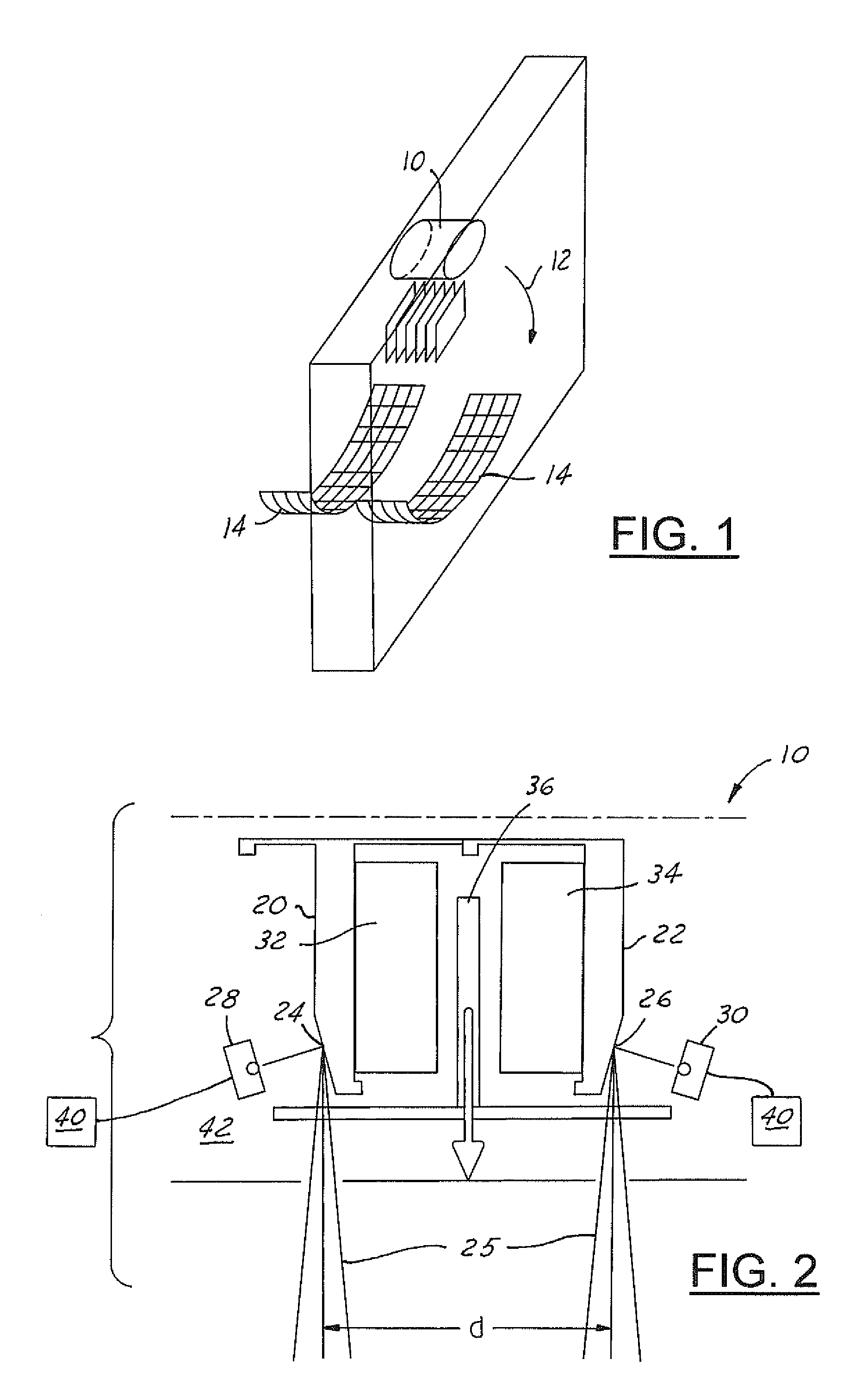
[0013]Referring to FIG. 1, there is shown the x-ray tube 10 of the present invention on a rotating gantry 12, along with a detector 14 as it would be arranged for a volume CT application. While the embodiment shown is for a volume CT application and includes two grid detectors, it should be noted that it is for example purposes only and one skilled in the art is capable of using the x-ray tube 10 in another application or substituting detectors and the arrangement thereof in a CT application without departing from the scope of the present invention. A collimator 16 collimates the x-rays from the focal points into planes of radiation. The gantry 12 rotates about an axis moving the x-ray tube 10 and the detector 14 along with it.

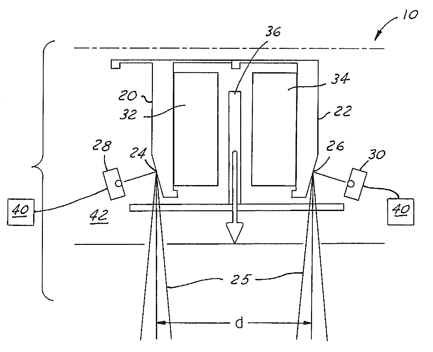
[0014]Referring to FIG. 2 a cross section of the x-ray tube 10 is shown. The x-ray tube is a vacuum tube and is typically surrounded by a shielded casing 18. Within the x-ray tube, there are two anodes 20, 22 each having a target 24, 26. The anodes 20, 22 are ...


PUM


Abstract

The present invention is an x-ray tube anode with two targets oriented back-to-back. The targets have separate and opposing cathodes. The targets are a fixed distance apart and rotate together on the same bearing shaft. The cathodes are mounted at either end of the vacuum tube. The cathodes may operate simultaneously or independent of each other based on the CT application.

Description

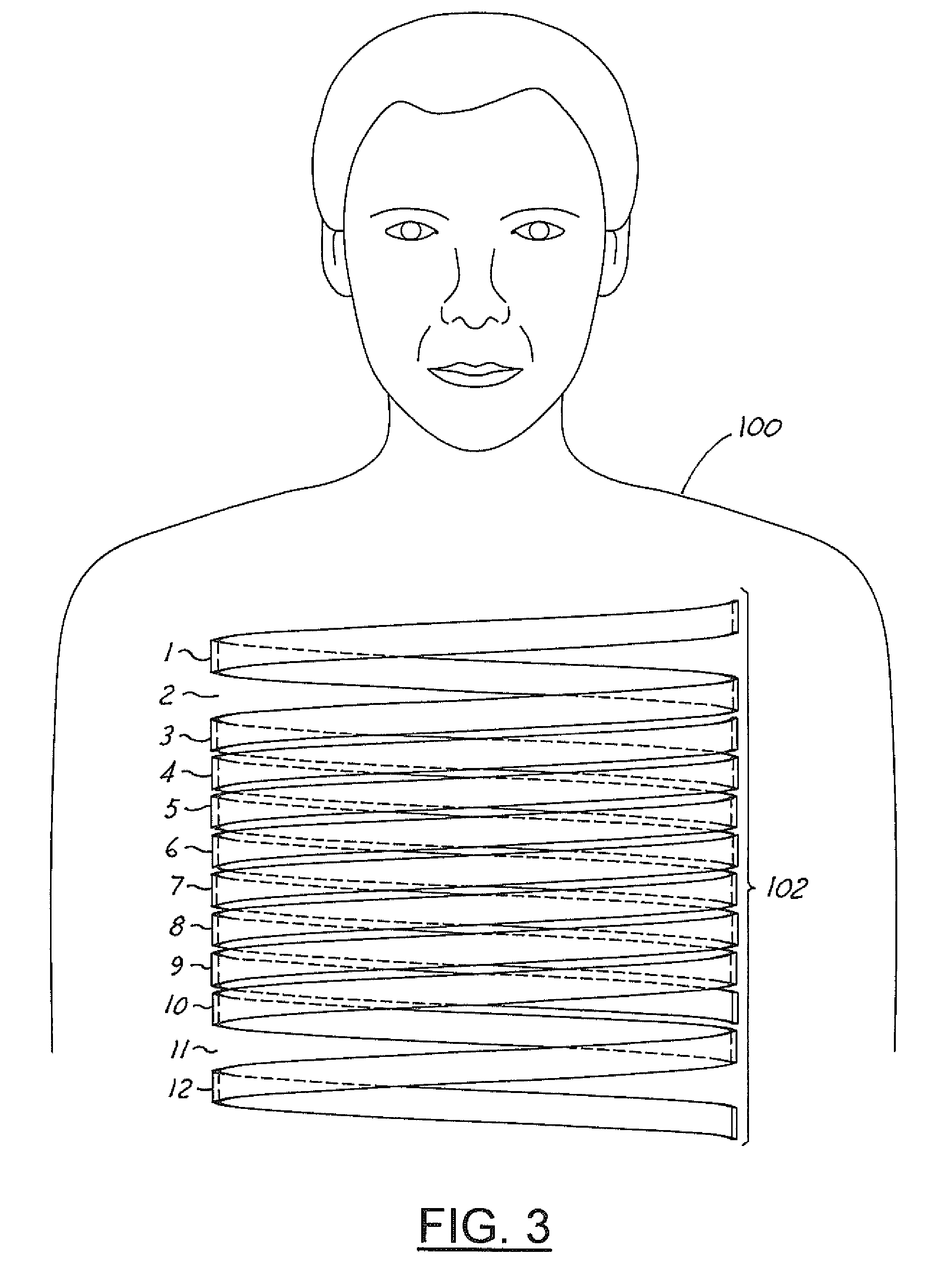
BACKGROUND OF INVENTION[0001]The present invention relates generally to x-ray tubes and more particularly to x-ray tubes for volume computed tomography (CT) protocols.[0002]A volume CT scan is typically generated by rotating an x-ray tube around an examination area while a subject is moved through the examination area. Cardiac screening, lung cancer evaluation and other volume CT protocols require larger coverage areas. Current technology requires lengthy scan times and requires elongated breath hold times from a subject in order to image an entire region of interest.[0003]Several techniques have been applied in order to increase coverage of the x-ray anode, thereby reducing scan time and improving the subject's comfort level. For example, in one technique, x-rays are collimated from a single focal spot into two or more planes of radiation. However, the planes are not parallel and only a small number of planes are generated. Therefore, several revolutions are needed to cover any sig...

Claims


Application Information

Patent Timeline
Patent Type & Authority Patents(United States)
IPC IPC(8): H01J35/08G21K5/08A61B6/03H01J35/06H01J35/10
CPCA61B6/032A61B6/4014A61B6/4007H01J35/10A61B6/027A61B6/035A61B6/4085H01J2235/1204A61B6/4488
Inventor JEN, SHERMAN CHIH-YEEVERMILYEA, MARK ERNEST
Owner GE MEDICAL SYST GLOBAL TECH CO LLC
Learn More