Image processing apparatus

Inactive Publication Date: 2006-02-21
CANON KK
View PDF12 Cites 16 Cited by
  • Summary
  • Abstract
  • Description
  • Claims
  • Application Information

AI Technical Summary

Benefits of technology

[0022]It is an object of the present invention to eliminate variation among images to thereby

Problems solved by technology

This leads to the following problems.
For example, in a normal medical spot, since it is very difficult to acquire the gain variation data for every x-ray sensing, the gain variation data is acquired by the x-ray sensing once a day.
The above-mentioned time difference in the data acquirement may results in change of the environments (temperature, humidity or the like) where the data is acquired, and thus leads to the possibility that change may occur in the characteristic of the sensor pan

Method used


Image

  • Image processing apparatus
  • Image processing apparatus
  • Image processing apparatus

Examples


first embodiment

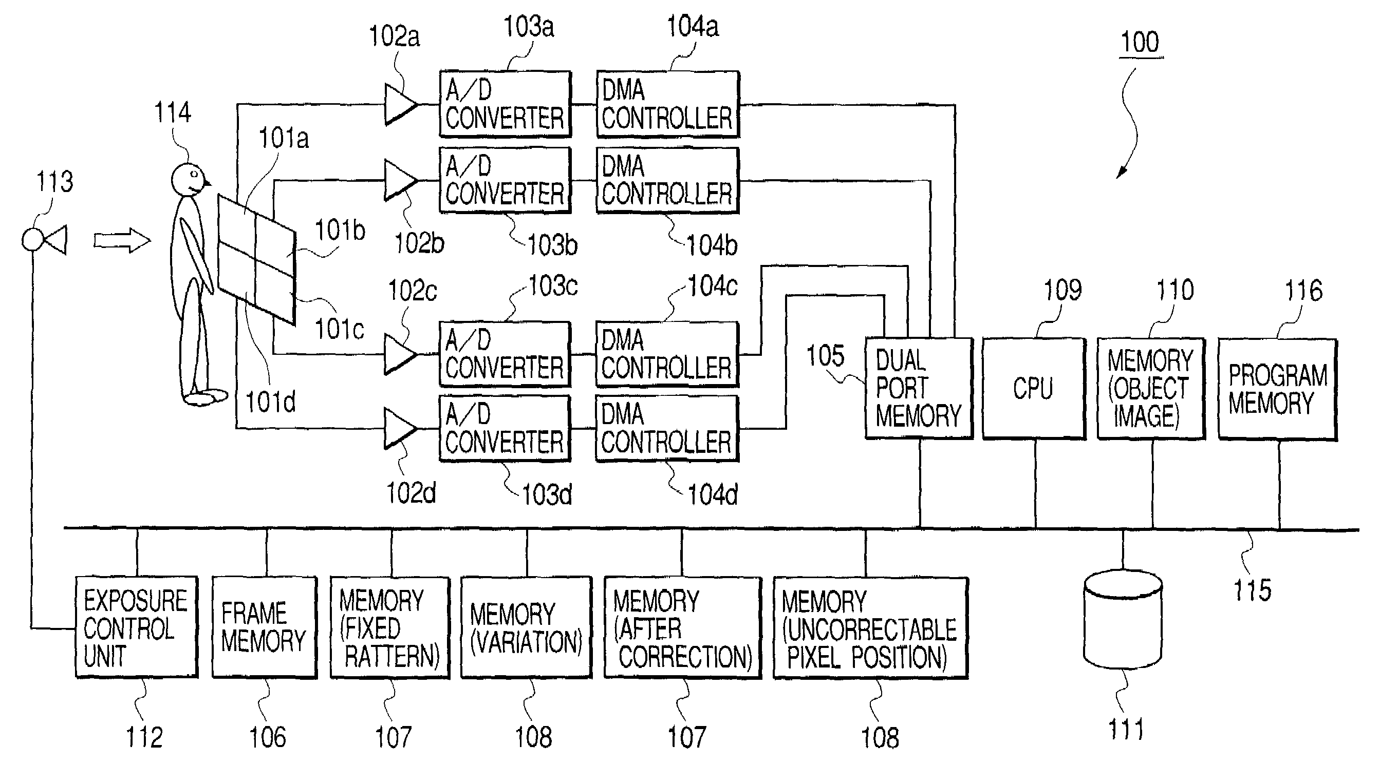
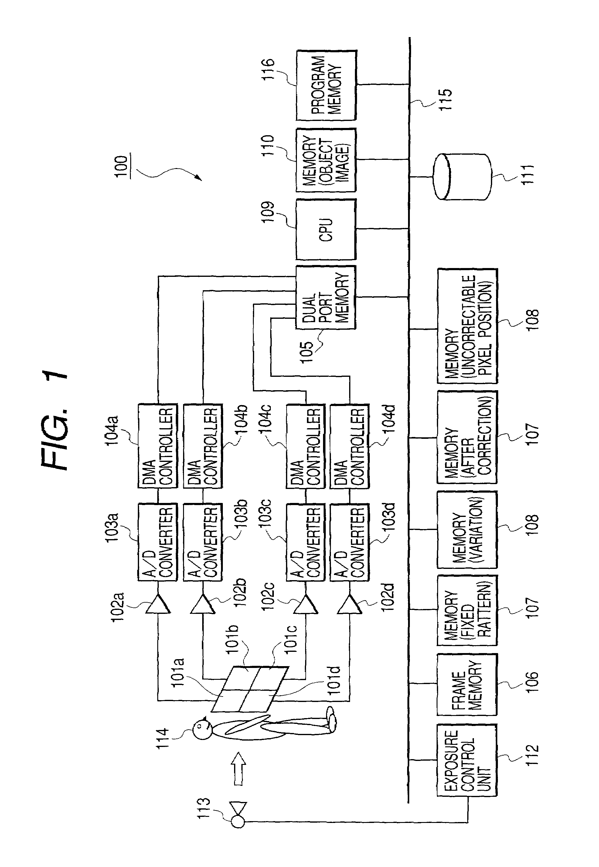
[0051]In a first embodiment, the present invention is applied to, for example, an x-ray sensing apparatus 100 shown in FIG. 1.

[0052]Prior to the specific description of the x-ray sensing apparatus 100 in this embodiment, a characteristic function implemented by the x-ray sensing apparatus 100 will be described.

[0053]The x-ray sensing apparatus 100 is an apparatus that is so designed as to acquire a single image from the assembly of a plurality of segment images that are acquired by divisionally driving a sheet of sensor panel, and particularly has a function of selecting two adjacent segment images from the plurality of segment images, adjusting the offset between those segment images to form one new portion, and repeatedly executing such a process to unify these segment images into one final image in which the boundary is not visible.

[0054]Hereinafter, the characteristic function of the x-ray sensing apparatus 100 will be specifically described.

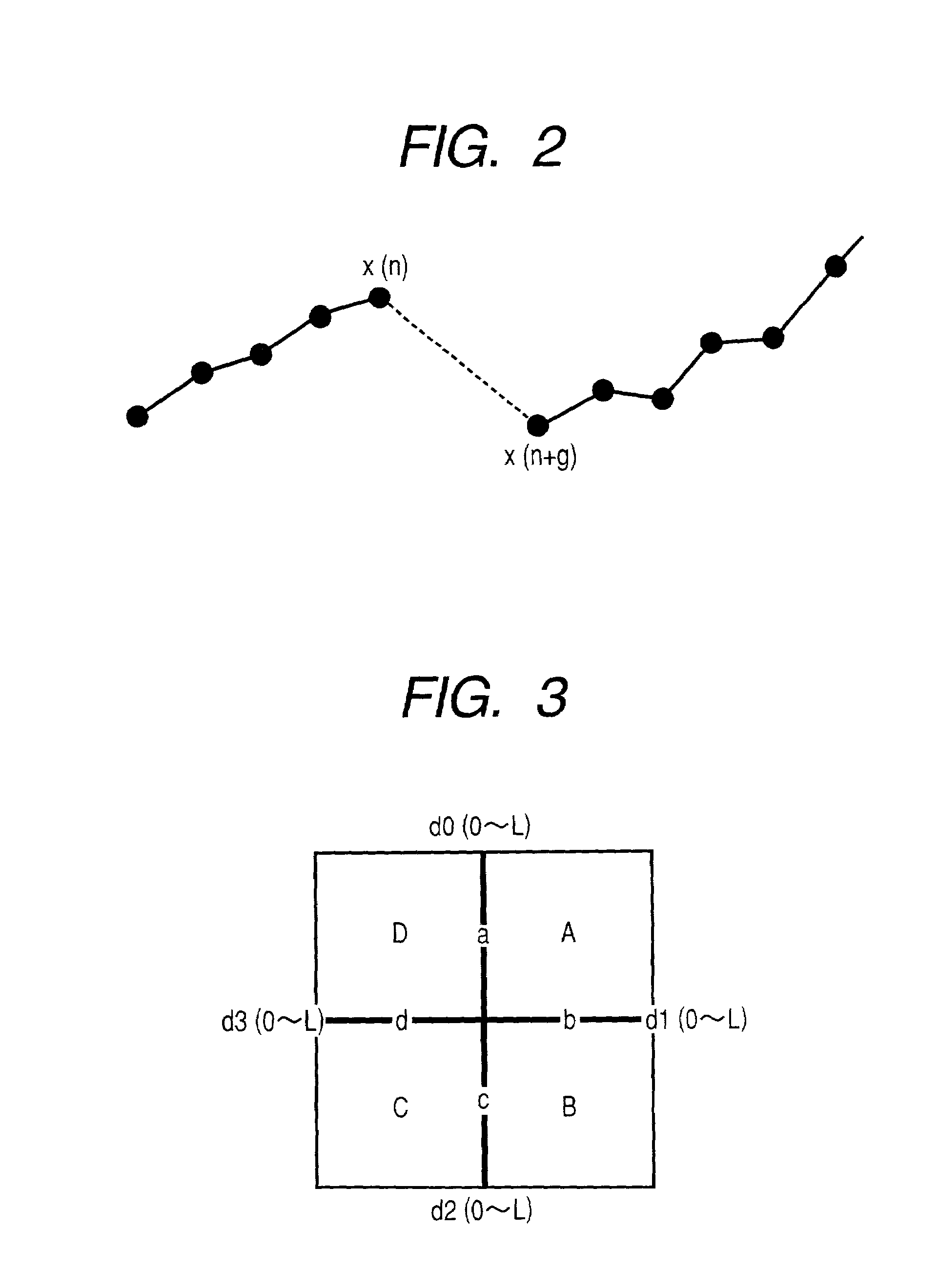
(1) First, a Substantial Step Value o...

second embodiment

[0174]Subsequently, the present invention will be described below.

[0175]In this embodiment, in the case where the offset components of the partial image is not uniform within the partial image, the step value sequence is not represented by a fixed value (the maximum frequency value, the average value or the like), but the step value sequence between two partial images is fitted by a function of the low degree of freedom to prepare a step function, and the step function is divided into two and added to both of the partial images, to thereby unify two partial images.

[0176]Note that, in this embodiment, the step function is prepared, and the step function is divided into two and added to both of the partial images. However, for example, it is possible that the step function is added to one partial image, and a function resulting from reversing the sign of the step function is added to the other partial function.

[0177]FIGS. 13A to 13C schematically show this embodiment.

[0178]First, as s...

third embodiment

[0195]Subsequently, the present invention will be described below.

[0196]In this embodiment, for example, in the x-ray sensing apparatus 100 shown in FIG. 1, the four partial panels 101a to 101d are replaced with nine partial panels to acquire nine partial images (00) to (22) as shown in FIG. 15A, and two partial images which are independent from each other are sequentially selected from those partial images (00) to (22) and combined together.

[0197]More specifically, the nine partial images (00) to (22) that are in a state shown in FIG. 15A are unified as indicated in the order of FIG. 15B, 15C, 15D and 15E. In this situation, as shown in FIG. 15D, it should be noted that when two partial images are formed, the boundary of both the partial images is linear.

[0198]After the unified state shown in FIG. 15D, the process shown in FIG. 11 is executed to add the repair at the step position. The repair in the vicinity of the boundary in this situation may be conducted every time the process ...


PUM


Abstract

An image processing apparatus includes an image processing circuit having a first mode that corrects an offset between a first image and a second image that are adjacent to each other to synthesize the first image and the second image into a new third image, and a second mode that corrects an offset between the third image and a fourth image that are adjacent to each other to synthesize the third image and the fourth image into a new fifth image.

Description

BACKGROUND OF THE INVENTION[0001]1. Field of the Invention[0002]The present invention relates to a technique for synthesizing a plurality of images into one image.[0003]2. Related Background Art[0004]Up to now, for example, as an x-ray sensing apparatus that creates an image from the amount of x-rays that have passed through the interior of an object to be sensed (the interior of a human body, etc.), there has been proposed a device in which a spatial distribution of the intensity of the x-rays that have passed through the object to be sensed is converted directly into an electric signal by a large-sized x-ray sensor panel, and the electric signal is converted into a digital value through analog-to-digital (A / D) conversion so that the x-ray image of the object to be sensed is available to image saving, image processing, image observation or the like as a digital image.[0005]As the above-mentioned x-ray sensor panel, for example, in the case where the object to be sensed is a chest r...

Claims


Application Information

Patent Timeline
IPC IPC(8): G06K9/00G06T5/50
CPCG06T5/50
Inventor INOUE, HITOSHI
Owner CANON KK
Why Eureka
Try Eureka