Vision prosthesis for the blind and method for implementing same

Active Publication Date: 2006-02-21
NEWSOUTH INNOVATIONS PTY LTD
View PDF4 Cites 40 Cited by
  • Summary
  • Abstract
  • Description
  • Claims
  • Application Information

AI Technical Summary

Problems solved by technology

Vision loss and/or blindness results when the neurons in the retina are damaged or destroyed, e.g., by disease.
While active electrodes attached to the retina, as in the Humayun and Chow patents, will stimulate the retina and produce light perception, studies indicate that electrodes in direct physical contact with the retina may cause irreversible damage to neurons and tissue.
According

Method used


Image

  • Vision prosthesis for the blind and method for implementing same
  • Vision prosthesis for the blind and method for implementing same

Examples


Embodiment Construction

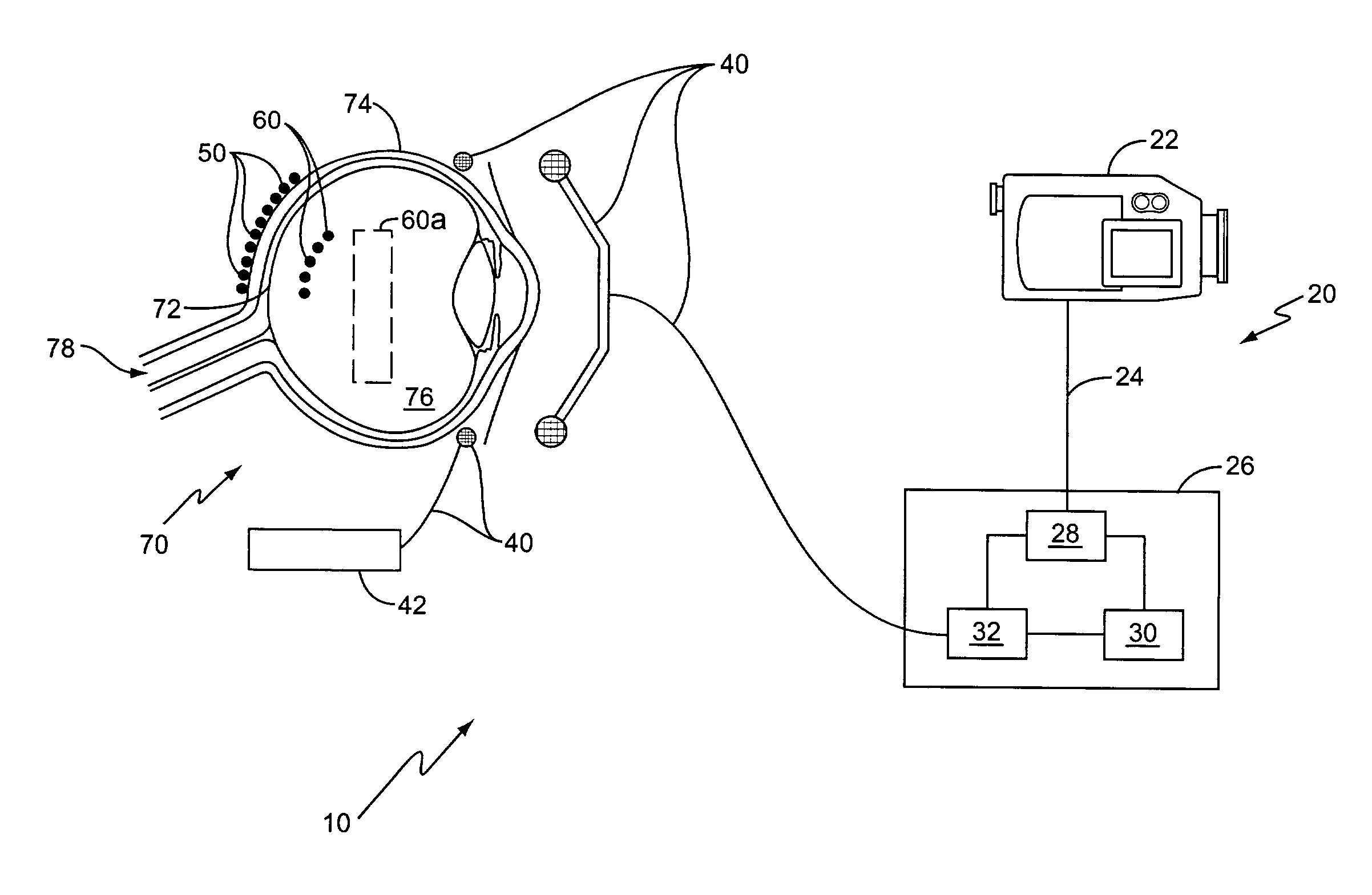
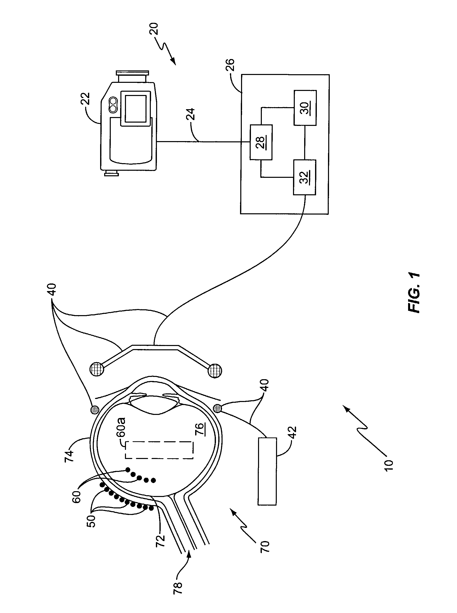
[0014]FIG. 1 illustrates a visual prosthesis system, generally indicated by numeral 10, according to the present invention. Visual prosthesis system 10 includes various components, both internal and external to the eye 70 and the patient. Eye 70 includes retina 72, sclera 74, vitreous chamber 76, and optic nerve 78. For simplicity, other areas of the eye such as the cornea, lens, iris, and conjunctiva are not referenced in FIG. 1.

[0015]Visual prosthesis system 10 includes imaging electronics 20, data link 40, stimulating electronics 42, stimulating electrodes 50, and reference electrodes 60. The imaging electronics 20 include a camera or other image capture device 22 connected to processing electronics 26 via a data communications line 24. Processing electronics 26 include image processor 28, memory 30, and encoder 32.

[0016]In exemplary embodiments, image capture device 22 captures an image from the environment and transfers the image to the image processor 28 within processing elec...


PUM


Abstract

The invention described herein comprises an electronic retinal prosthesis for the treatment of some forms of blindness in animals (humans inclusive) wherein surviving retinal neurons of an intact, damaged, or diseased retina, may be physiologically activated by way of electrical stimulation delivered from electrodes placed in biologically sustainable positions so as to produce the perception of light in said animal.

Description

RELATED APPLICATIONS[0001]This application claims priority under U.S.C. §119(e) from provisional application No. 60 / 331,579 entitled “Vision Prosthesis for the Blind, Sustainable Electrode Positioning and Method for Implementing the Same” filed 20 Nov. 2001.FIELD OF THE INVENTION[0002]The present invention relates generally to a method and apparatus for treating some forms of blindness, and more particularly to a method and apparatus for stimulating the retina in the eye.BACKGROUND OF THE INVENTION[0003]The eyes enable light perception in animals. The animal perceives visual images when an eye senses light and sends visual information to the brain via the optic nerve. Each eye includes the sclera, retina, pupil, lens, and a vitreous chamber filled with vitreous humor. The outer layer of the eye includes an opaque portion, the sclera, that is continuous with a transparent portion, the cornea, for receiving light. The iris regulates the light, entering the eye through the cornea, that...

Claims


Application Information

Patent Timeline
IPC IPC(8): A61N1/20
CPCA61N1/36046A61N1/0543
Inventor SUANING, GREGG J.LOVELL, NIGEL H.KERDRAON, YVES K.
Owner NEWSOUTH INNOVATIONS PTY LTD
Why Eureka
Try Eureka