Zero-knowledge proving system and method

a technology of knowledge proving and zero knowledge, applied in the field of zero knowledge proving techniques, can solve the problems of leaking important information, the prover is unable to prove the inequality alone,

Inactive Publication Date: 2006-02-21
NEC CORP
View PDF7 Cites 15 Cited by
  • Summary
  • Abstract
  • Description
  • Claims
  • Application Information

AI Technical Summary

Benefits of technology

[0007]An object of the present invention is to provide a zero-knowledge proving system and method allowing the same protocol to be used to prove the equality or inequality of discrete logarithms and allowing the prover solely to prove it without leaking important information.

Problems solved by technology

Especially, the system of proving the inequality cannot be performed without the verifier and therefore it is impossible for the prover solely to prove the inequality.
Although this scheme allows the prover solely to prove both the equality and inequality and the efficiency thereof has been qualitatively analyzed, it has a disadvantage of leaking important information.

Method used


Image

  • Zero-knowledge proving system and method
  • Zero-knowledge proving system and method
  • Zero-knowledge proving system and method

Examples


embodiments

1. First Embodiment

[0099]1.1) System Configuration

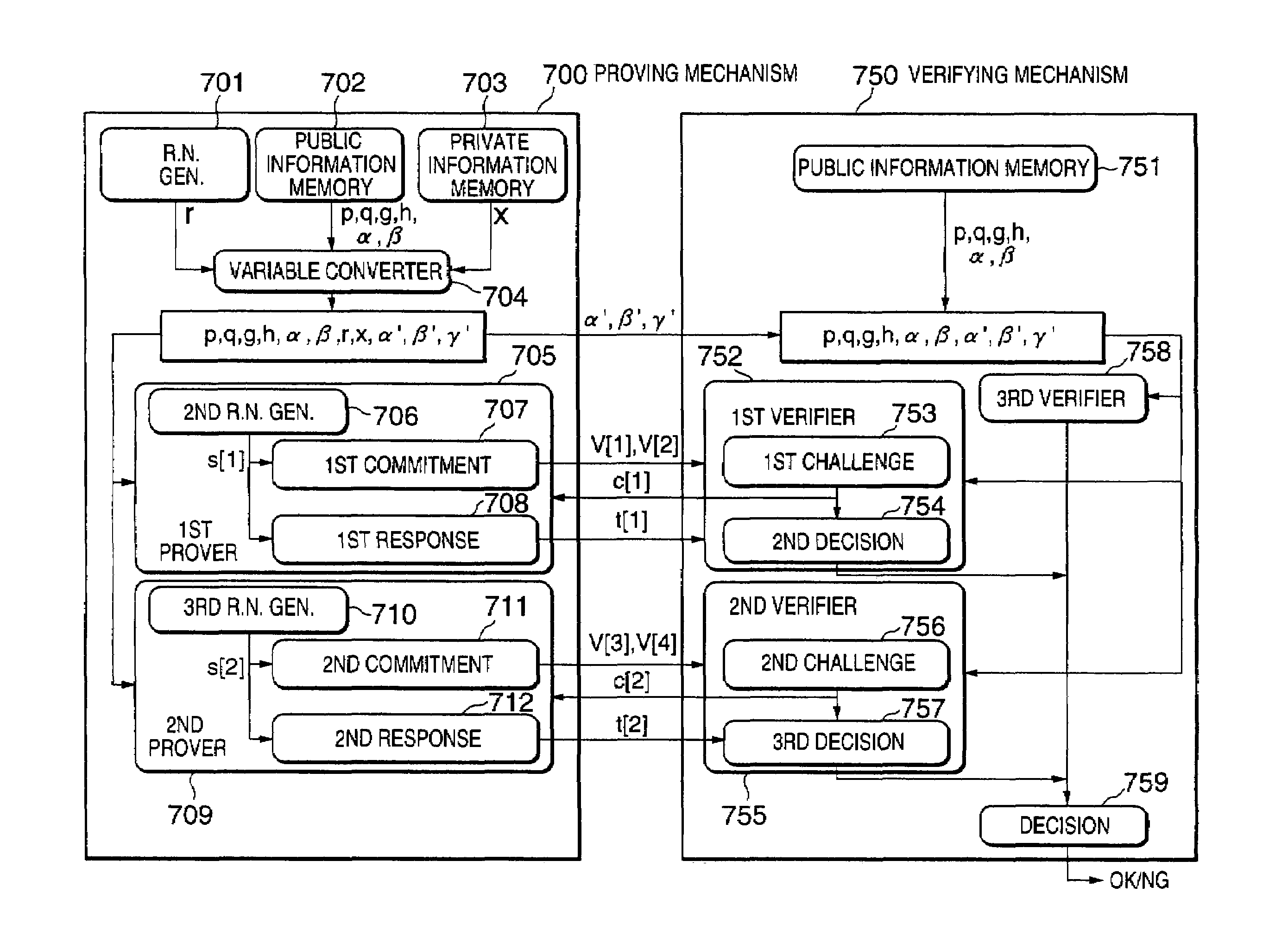
[0100]Referring to FIG. 7, the system has a proving mechanism 700 and a verifying mechanism 750. The proving mechanism 700 includes a random number generator 701, a public information memory 702, a private information memory 703, a variable converter 704, a first prover 705 and a second prover 709. The first prover 705 includes a second random number generator 706, a first commitment section 707, and a first response section 708. The second prover 709 includes a third random number generator 710, a second commitment section 711, and a second response section 712. The random number generator 701, the variable converter 704, the first prover 705 and the second prover 709 may be implemented by running corresponding programs on a computer.

[0101]The verifying mechanism 750 includes a public information memory 751, a first verifier 752, a second verifier 755, a third verifier 758, and a decision section 759. The first verifier 752 includes...

second embodiment

2. Second Embodiment

[0126]2.1) System Configuration

[0127]Referring to FIG. 8, the system according to the second embodiment includes a proving mechanism 800 and a verifying mechanism 850, in which a first prover 801 and a first verifier 851 are different from those of the first embodiment as shown in FIG. 7, Therefore, FIG. 8 shows only the first prover 801 and the first verifier 851, and other functional blocks are the same as shown in FIG. 7.

[0128]The first prover 801 includes a second random number generator 802, a first commitment section 803, and a first response section 804. The first verifier 851 includes a first challenge preparation section 853, a first challenge section 854 and a second decision section 855. As in the case of the first embodiment, the first prover 801 and a first verifier 851 may be implemented by running corresponding programs on a computer.

[0129]The first prover 801 and the first verifier 851 communicate with each other such that first challenge preparat...

third embodiment

3. Third Embodiment

[0139]3.1) System Configuration

[0140]Referring to FIG. 9, the system according to the third embodiment includes a proving mechanism 900 and a verifying mechanism 950, in which a first prover 901 and a first verifier 951 are different from those of the first embodiment as shown in FIG. 7. Therefore, FIG. 9 shows only the first prover 901 and the first verifier 951, and other functional blocks are the same as shown in FIG. 7.

[0141]The first prover 901 includes a second random number generator 902, a first commitment section 903, a first automatic challenge section 904, a first response section 905, and a first proven text sending section 906. The first verifier 951 includes a first automatic challenge section 952 and a second decision section 953.

[0142]The first commitment section 903 uses a random number s[1] to convert α and β to produce first commitments v[1] and v[2]. The first automatic challenge section 904 produces first automatic challenge c[1] from the firs...


PUM


Abstract

A zero-knowledge proving system includes a proving mechanism for proving equality or inequality of two discrete logarithms and a verifying mechanism for verifying said equality or inequality. The proving mechanism stores public information including a designated operation scheme, two input numbers α and β, and two predetermined bases g and h, private information x which is a discrete logarithm of α to the base g. After converting α, β and h to produce α′, β′ and γ′ as follows: α′=αr; β′=βr; and γ′=hxr, the equality of a logαα′ and logββ′ and the equality of loggα′ and loghγ′ are proved. The verifying mechanism verifies the equality of a logαα′ and logββ′ and the equality of loggα′ and loghγ′. Then, the received β′ and γ′ are checked to determine the equality or inequality thereof, and it is determined whether the proof is acceptable, depending on the verification and the check results.

Description

BACKGROUND OF THE INVENTION[0001]1. Field of the Invention[0002]The present invention relates to zero-knowledge proving techniques for proving the equality or inequality of (discrete logarithms, which is suitable for use in undeniable signatures.[0003]2. Description of the Related Art[0004]Undeniable signatures proposed by Chaum have an important property such that a signer cannot deny the validity of a self-generated signature but a forged signature. The undeniable signature schemes like this make use of the group operation of an order-q group G on modulo p, where p and q are prime and have a relationship of q|(p−1). When y=gx is an element of the group G, the signer uses the generator g as a public key and x as a private key. A signature on a message m is obtained by calculating SIG=mx, where x is the private key. For (m, SIG), the validity of the signature can be decided by proving the equality of the discrete logarithm x of the public key: y=gx and the discrete logarithm x′ of S...

Claims


Application Information

Patent Timeline
Patent Type & Authority Patents(United States)
IPC IPC(8): G06F17/10G09C1/00H04L9/32
CPCH04L9/0643H04L9/0662H04L9/3271H04L9/3218H04L9/3013
Inventor FURUKAWA, JUNSAKO, KAZUEOBANA, SATOSHI
Owner NEC CORP
Why Eureka
Try Eureka