Fastening device

a technology of fastening device and clamping rod, which is applied in the direction of door/window fittings, multi-purpose tools, construction, etc., can solve the problems of curtain tearing before, no patent claims or discloses, teaches or suggests an apparatus, etc., and achieves smooth movement of the fastening device, facilitate the sliding motion of the coupling, and slide easy

Inactive Publication Date: 2006-02-28
ALLURE HOME CREATION
View PDF38 Cites 39 Cited by
  • Summary
  • Abstract
  • Description
  • Claims
  • Application Information

AI Technical Summary

Benefits of technology

[0027]In a preferred embodiment of the invention, the coupling means will be shaped as half of an oval having its center of gravity positioned at the quarter point of the oval and the weight of the sheet material will force the coupling means to slidably couple to a substantially fixed object and maintain its balance.
[0028]In another embodiment, the coupling means is in an “S” shape and optionally having at least one bead disposed on the opposite surface of the receiving surface of the coupling means to facilitate smooth movement of the fastening device to the substantially fixed object.
[0029]In yet another embodiment, the coupling means is in a circular and / or an oval shape that is formed by connecting two half circles and / or two half ovals connected by a hinge on one side and a locking mechanism on another. The locking mechanism is generally comprised of two engaging surfaces, one having a protrusion and the other having a recess to receive the protrusion. The exterior surface of the receiving surface of the coupling means optionally has beads disposed on it in order to facilitate the sliding motion of the coupling means, hence the fastening device with a sheet material, preferably a shower curtain, to slide easily on a substantially fixed object, preferably a shower curtain rod.
[0030]In a preferred embodiment, the attachment means is attached to a coupling means through a recess disposed on the bridge of the attachment means and this enables the attachment means to be rotatably attached to the coupling means. Thus, in addition to connecting the sheet material, preferably a shower curtain, to a substantially fixed object, it can also minimize shelf space when packaged for sale by rotating the attachment means to be on the same plane with the coupling means.

Problems solved by technology

The compressive clamping applied to the first curtain edge by the fastener in the second position exceeds the shear strength of the curtain such that a force which exceeds the shear strength of the curtain applied to the curtain first edge will result in the tearing of the curtain before the release of the edge of the curtain from the position between the first and second clamping surfaces.
However, none of these patents claims or discloses, teaches or suggests an apparatus capable of attaching the shower curtain to a rod without having the user have to assemble the connection between the shower curtain and the shower curtain ring and then the shower curtain ring to the shower curtain rod all in one setting while standing on the edge of the bathtub.

Method used


Image

  • Fastening device
  • Fastening device
  • Fastening device

Examples


embodiment 10

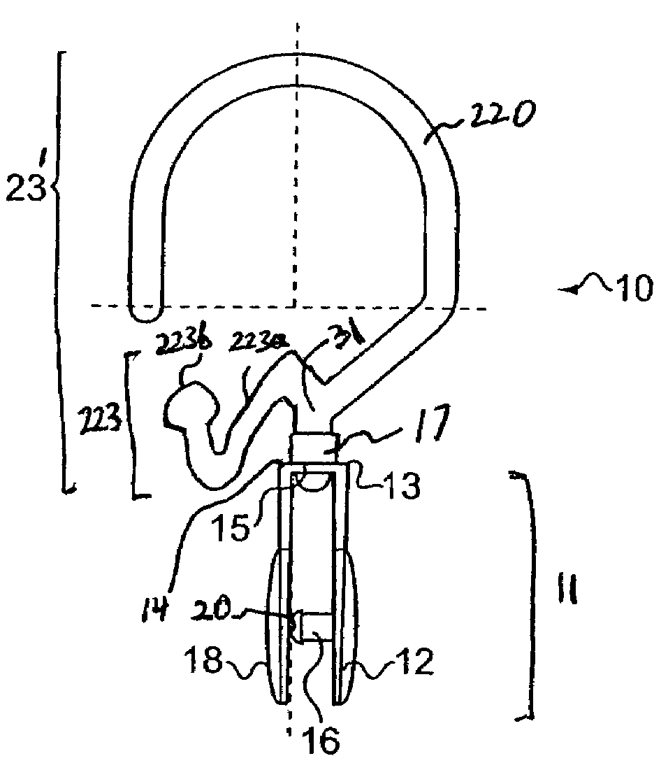
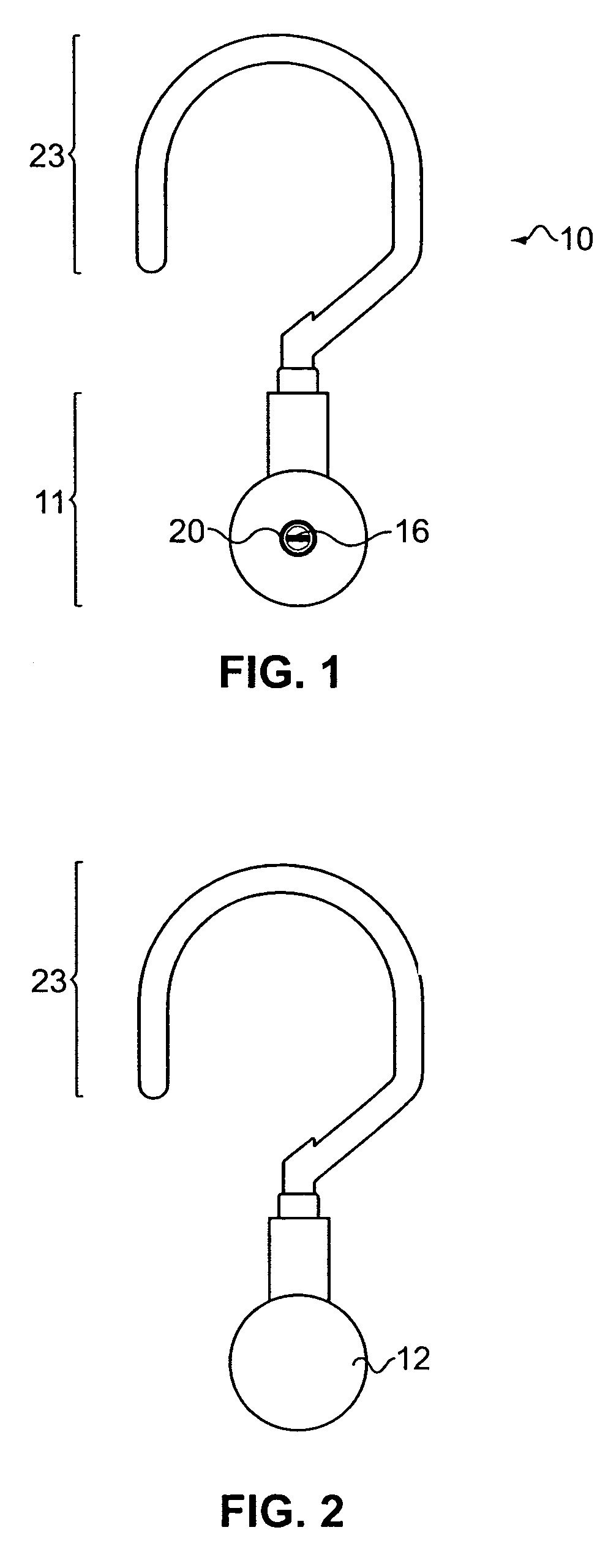
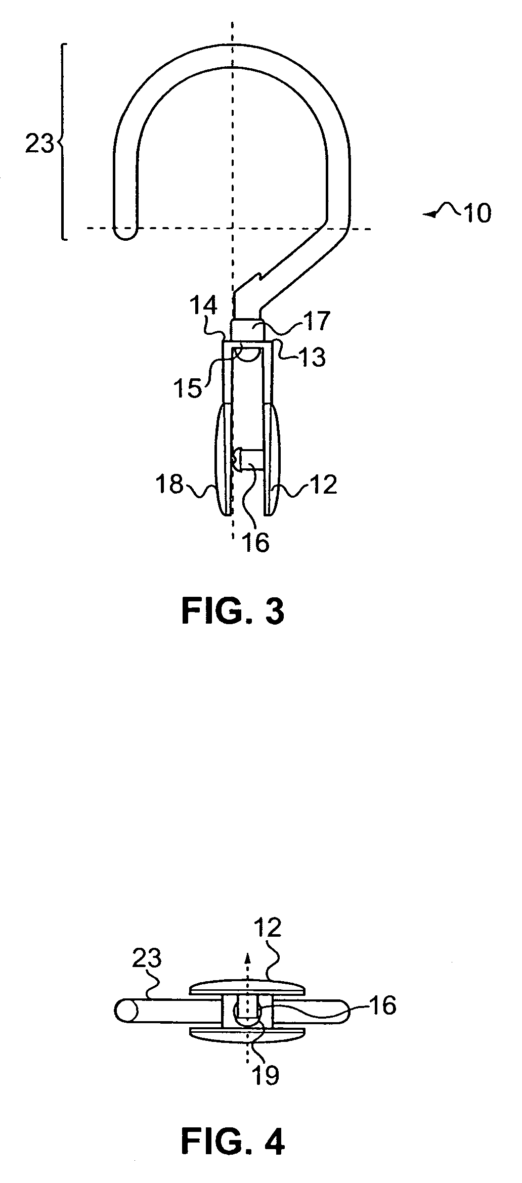
[0068]Reference is made to all of the Figures herein as preferred embodiment. FIG. 1 shows a fastening device 10 having a coupling means 23 and an attachment means 11 comprised of an extending member 16 matingly engaged with recess 20. FIG. 2 shows the front side of the fastening device 10 wherein the attachment means 11 is comprised of a first elongated member 12 having an extending member 16 on an interior surface of the first elongated member 12. FIG. 3 shows an exploded side view of the embodiment 10 having a half oval-shape coupling means 23 removably attached to an attachment means having a sleeve 17 disposed on a recess 21 which is positioned on a bridge 15, and first ends of the first and second elongated members 13 and 14 connected by the bridge 15. There is an extending member 16 protruding from the inside surface of the second end of the first elongated member 12. The extending member 16 has a bulbous head 19 that has a circumference slightly larger than recess 20 in orde...

second embodiment

[0073]FIG. 11 shows the present invention whereby the coupling means 33 is S-shaped and the exterior of the receiving surface optionally has circular beads 41. The circular beads disposed on the opposite side of the receiving surface facilitate the movement of the fastening device on any object it couples to. The coupling means 33 has an extended second portion 31 having a bulbous head 30 that pierces the recess 21 disposed on bridge 15 to connect with attachment means 11 via sleeve 17 and recess 21. The attachment means has extending member 16 and bulbous head 19 that is slightly larger in diameter.

third embodiment

[0074]FIG. 12 shows the present invention whereby the coupling means 43 is S-shaped and the exterior of the receiving surface 27 has rectangular beads 42 disposed on it in order to facilitate movement of the fastening device when coupled to a substantially fixed object. The coupling means 43 has an extended second portion 31 that facilitates the engagement of the attachment means to the coupling means.


PUM


Abstract

Claimed and disclosed is a fastening device that can fasten itself to a sheet material and at the same time couples itself to an object, comprising a coupling means for slidably coupling the device to a substantially fixed object and an attachment means for attaching the sheet material to the device. The coupling means defines a receiving surface at a first portion, has an extended second portion thereof which is rotatably connected to an attachment means for attaching an object to the device. The coupling means further has a receiving means extending outwardly from the second portion of the coupling means to receive a material. The receiving means having a concavely-shaped first end and an enlarged second end to receive a material. The enlarged second end ensures the material stays securely in the concavely-shaped first end. The attachment means comprising two elongated outer members connected by a bridge, a first outer member comprising an extending member on its interior surface and extends toward a corresponding recess disposed on an interior surface of a second elongated outer member. The bridge of the attachment means defines a recess with a sleeve to receive the extended second portion of the coupling means to form the fastening device as claimed and disclosed in the present invention.

Description

CROSS-REFERENCE TO RELATED APPLICATION[0001]This application is a continuation-in-part of U.S. patent application Ser. No. 09 / 988,114 which was filed on Nov. 16, 2001, now U.S. Pat. No. 6,698,061 allowed Sep. 12, 2003, and which is hereby incorporated by reference.FIELD OF THE INVENTION[0002]The present invention relates to a fastening device. More specifically, the present invention teaches and discloses a shower curtain connector that has, at its first end, a fastener to receive an aperture of a sheet material, preferably a shower curtain and, at its second end, at least one coupling means such as a curved hook that can hang on a shower curtain rod. The second end can also optionally have a second coupling means to receive a sheath of material and / or any decorative item. The fastening device can be sized and colored as desired and can be made from any material that is flexible, springy yet sturdy and afford a degree of rigidity. Thus, it can be made from any plastic, resin, metal,...

Claims


Application Information

Patent Timeline
Patent Type & Authority Patents(United States)
IPC IPC(8): E05D15/00A47H13/04A47H13/12A47K3/38
CPCA47H13/04A47K3/38Y10T16/353Y10T16/3543Y10T16/355
Inventor HO, STANLEY
Owner ALLURE HOME CREATION
Why Eureka
Try Eureka