
Thruster device responsive to solar radiation and associated methods

Inactive Publication Date: 2006-02-28
AEROJET ROCKETDYNE OF DE +1
View PDF22 Cites 5 Cited by
  • Summary
  • Abstract
  • Description
  • Claims
  • Application Information

AI Technical Summary

Benefits of technology

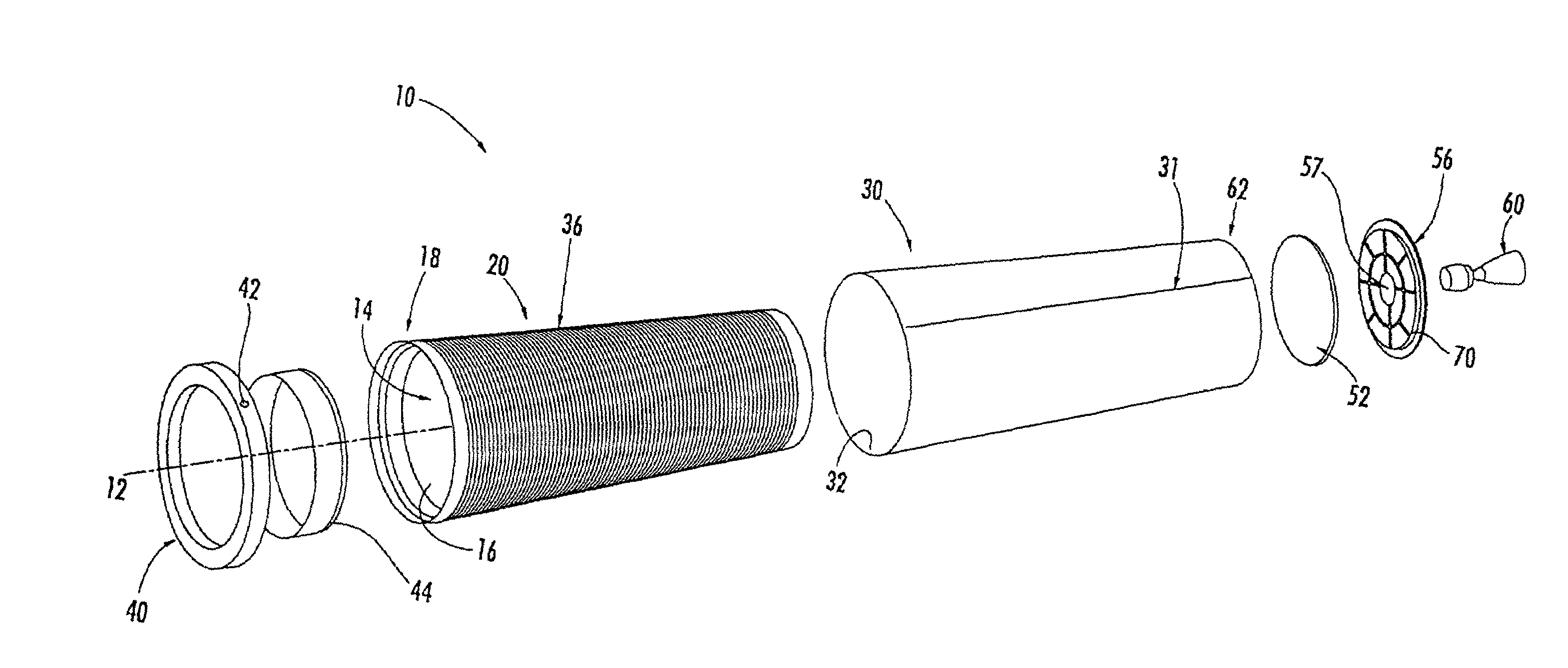
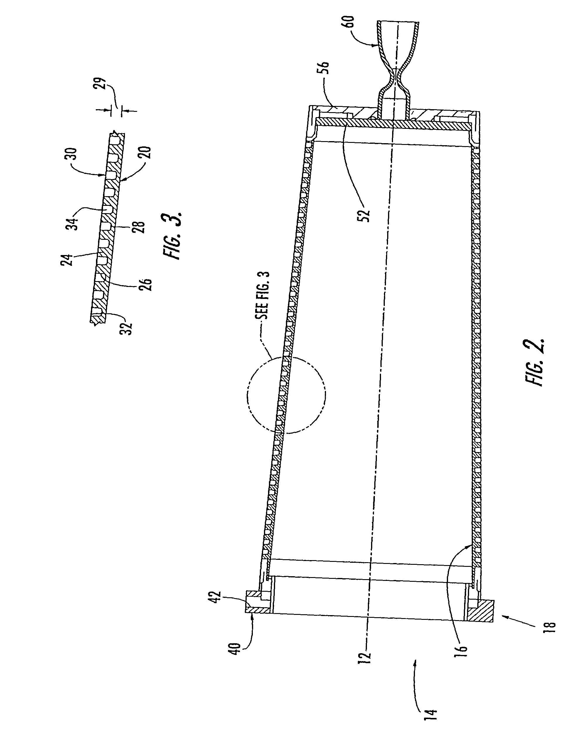
[0010]These and other needs are provided, according to the present invention, by a thruster device having frustoconical inner and outer layers and a flow passage interposed between the two layers. The flow passage can be defined by the inner layer, outer layer, or both layers. As such, the thruster device of the present invention provides a flow passage formed without having to wind a tube around a mandrel, thereby simplifying the fabrication process. Advantageously, the frustoconical configuration of the inner and outer layers of the thruster device of the present invention allows for easy assembly of the thruster device with minimal risk of damaging the flow passage due to chafing between the inner and outer layers. Thus, the resulting thruster device can typically be fabricated relatively inexpensively.
[0014]Advantageously, the present invention provides a thruster device and associated methods that overcomes the shortcomings of conventional thrusters discussed above. In particular, the thruster device of the present invention provides a flow passage that is preferably defined by the inner and / or outer layers, instead of requiring a tube to be wound around a mandrel as in some conventional thruster devices. Furthermore, the thruster device of the present invention is easy to assemble, since the frustoconical configuration of the inner and outer layers do not abrade against one another as the outer layer is positioned over the inner layer. As such, the thruster device of the present invention is improved in both cost and performance. In particular, the design of the thruster device significantly simplifies the fabrication process compared to conventional thrusters by reducing the number of parts required to form the flow passage and eliminating the costly and time consuming process of welding and winding tubes about a mandrel to form the flow passage. In addition, the design of the thruster device reduces the likelihood of damaging the flow passage during assembly by reducing, if not eliminating, abrading and other deleterious contact between the inner and outer layers as the inner layer is inserted into the outer layer. Thus, the thruster device of the present invention has reduced fabrication costs. As a result, the propellant can be directed to the outlet in a more efficient manner, which results in higher performance of the thruster device. Advantageously, the improved performance of the thruster device allows for greater payload capacity along with lower costs per firing cycle.

Problems solved by technology

While the use of thruster devices is known, conventional thruster devices can be relatively difficult to manufacture.
However, as the tubes are wound around the mandrel, the metal tubes work harden and are very difficult to form to the desired shape.
Thus, this design requires a tedious, time-consuming and costly fabrication process.
In particular, chafing can damage the seal between the grooves forming the channel, which can have a deleterious effect on the flow of propellant and result in a loss of thrust.
However, this thruster design has not been proven experimentally.

Method used


Image

  • Thruster device responsive to solar radiation and associated methods
  • Thruster device responsive to solar radiation and associated methods
  • Thruster device responsive to solar radiation and associated methods

Examples


Embodiment Construction

[0021]The present invention now will be described more fully hereinafter with reference to the accompanying drawings, in which preferred embodiments of the invention are shown. This invention may, however, be embodied in many different forms and should not be construed as limited to the embodiments set forth herein; rather, these embodiments are provided so that this disclosure will be thorough and complete, and will fully convey the scope of the invention to those skilled in the art. Like numbers refer to like elements throughout.

[0022]Turning first to FIGS. 1–3, a thruster device 10 is provided for positioning objects in space, such as satellites. The thruster device utilizes solar energy to heat propellant, such as gaseous hydrogen, and direct the propellant through an outlet, such as nozzle. The expansion of the propellant through the outlet produces thrust, which is used by the satellite or other space-positioned object to maneuver between orbits or to maintain a particular loc...


PUM

PropertyMeasurementUnit
Flow rateaaaaaaaaaa

Abstract

A thruster device and associated methods are provided. The thruster device comprises a frustoconical inner layer and a frustoconical outer layer that surrounds the inner layer such that the inner and outer layers cooperate to define a spiral flow passage therebetween. An outlet, such as a nozzle, is attached to an exit end of the thruster device such that the outlet is in fluid communication with the spiral flow passage. In one embodiment, the thruster device includes an end flow cap that is also attached to the exit end and establishes the fluid communication between the spiral flow passage and the outlet. The end flow cap includes at least one channel for directing the propellant from the spiral flow passage to the outlet. The design of the thruster device allows the frustoconical inner and outer layers to be assembled without galling or damaging the spiral flow passage.

Description

CROSS-REFERENCE TO RELATED APPLICATIONS[0001]This application is a divisional of application Ser. No. 10 / 097,523, filed Mar. 14, 2002 now U.S. Pat. No. 6,745,466, and application Ser. No. 09 / 592,724, filed Jun. 13, 2000, now issued as U.S. Pat. No. 6,421,998, which are hereby incorporated in their entirety by reference.FIELD OF THE INVENTION[0002]The present invention relates to solar energy systems, and in particular relates to solar power propulsion systems which use thermal energy for propelling and powering a spacecraft.BACKGROUND OF THE INVENTION[0003]Thruster devices are often used in the space industry, particularly for low power applications such as orbital positioning of a spacecraft. In particular, a thruster device, such as a solar thruster, may be used for correcting or maintaining the orbit of a satellite. Another application of thruster devices is to change or alter the orbital path of a satellite in order to avoid detection by other satellites or ground tracking devic...

Claims


Application Information

Patent Timeline
IPC IPC(8): F03H1/00B64G1/40B64G1/42B64G1/44F02K9/42F03H99/00F24S20/20
CPCB64G1/401B64G1/446F02K9/42F03H99/00F24J2/07Y10T29/49355B64G1/427Y02E10/41F05D2250/25F05D2260/20F05D2230/11F05D2300/13Y10T29/49995Y10T29/49346B64G1/402F24S20/20Y02E10/40
Inventor FRYE, PATRICK E.CARROLL, JOSEPH P.SHOJI, JAMES M.
Owner AEROJET ROCKETDYNE OF DE
Learn More