Cryogenic cooling system and method with cold storage device

a cryogenic refrigerator and cold storage technology, applied in the field of cryogenic refrigeration system, can solve the problems of affecting the operation of the backup refrigerator, affecting the operation of the cooling system, and requiring repair or replacement, so as to prevent the temperature of the thermal load from rising, reduce the pressure, and reduce the complexity of control

Inactive Publication Date: 2006-02-28
GENERAL ELECTRIC CO
View PDF18 Cites 12 Cited by
  • Summary
  • Abstract
  • Description
  • Claims
  • Application Information

AI Technical Summary

Benefits of technology

[0005]The second method of resolving the problem of refrigeration failure is to provide a refrigeration system that includes redundant refrigerator unit(s). However, if a redundant unit is not started prior to the refrigeration failure, many minutes may have elapsed after it is started for the backup redundant unit to provide significant cooling. In that time the field winding can still potentially reach a quench temperature. Alternatively, the backup redundant refrigerator unit can be run continuously. The disadvantages of this second method include substantially increased costs to buy and operate the extra refrigerator units.
[0006]The third method of resolving the problem of refrigeration failure uses a storage tank with a second cryogen in a liquid state as the cooling source during refrigeration outage. This method is schematically shown in FIG. 6 which illustrates a refrigeration system having a storage tank 9 with liquid cryogen. The liquid cryogen will not rise above its saturation temperature until all of the liquid has turned to gas. This system has the following disadvantages:
[0011]Accordingly, there remains a need for a cryogenic refrigeration system which provides a very reliable, passive method / system for preventing the temperature of a thermal load from rising unacceptably during repair or replacement of a cryogenic refrigerator or its accompanying hardware.
[0014]In another aspect of the present invention, a method of providing a cooling fluid to an apparatus comprises cooling the fluid utilizing a cryogenic refrigerator to a first temperature when the cryogenic refrigerator is operating at a first refrigeration capacity and to a second temperature when the cryogenic refrigerator is operating at a second refrigeration capacity, the first temperature being lower than the second temperature and the first refrigeration capacity being higher than the second refrigeration capacity, communicating as part of a fluid circuit, the fluid cooled by the cryogenic refrigerator to a passive cold storage device having a porous matrix of material which directly contacts the cryogenic cooling fluid when the cryogenic cooling fluid passes through the passive cold storage device, the fluid cooling the passive cold storage device when the fluid has been cooled to the first temperature by the cryogenic refrigerator operating at the first refrigeration capacity and the passive cold storage device cooling the fluid when the fluid has been cooled to the second temperature by the cryogenic refrigerator operating at second refrigeration capacity, and communicating, as part of the fluid circuit the fluid from the passive storage device to the apparatus. The passive cold storage device may cool the fluid when the fluid has been cooled to the second temperature and while the refrigeration capacity of the cryogenic refrigerator is being changed to the first refrigeration capacity.

Problems solved by technology

Unfortunately, these cryogenic refrigerators (including their compressors) are subject to failures and therefore periodically require repair or replacement.
If the refrigerator fails, the temperature of the gas will rise and potentially allow the field winding to reach a high enough temperature to quench and cease to be superconducting.
Even if the system includes a backup refrigerator unit, it can take many minutes after it is started for the backup refrigerator to provide significant cooling.
In that time the field coil can still potentially reach a quench temperature.
First, reducing the thermal load reduces the reliability of the system associated with the thermal load.
For example, if the thermal load is a superconducting field winding of an electric generator, the power output of the electric generator must be rapidly reduced thereby resulting in an unreliable power supply.
Also, there is a risk that the thermal load may not be reduced fast enough to prevent damage to the object being cooled.
For example, there is a risk of quench followed by permanent degradation of the superconducting field winding.
However, if a redundant unit is not started prior to the refrigeration failure, many minutes may have elapsed after it is started for the backup redundant unit to provide significant cooling.
In that time the field winding can still potentially reach a quench temperature.
The disadvantages of this second method include substantially increased costs to buy and operate the extra refrigerator units.

Method used


Image

  • Cryogenic cooling system and method with cold storage device
  • Cryogenic cooling system and method with cold storage device
  • Cryogenic cooling system and method with cold storage device

Examples


Embodiment Construction

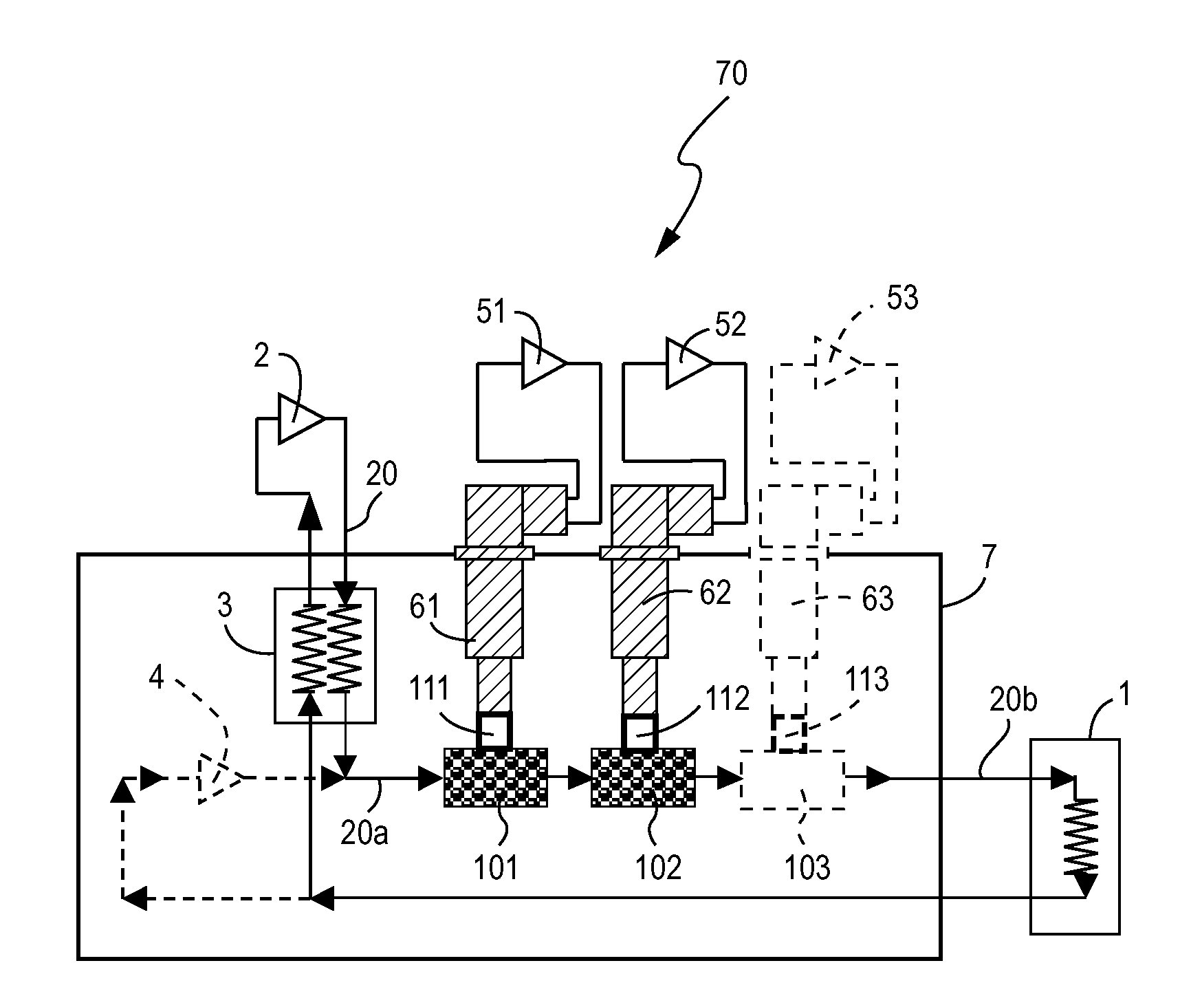
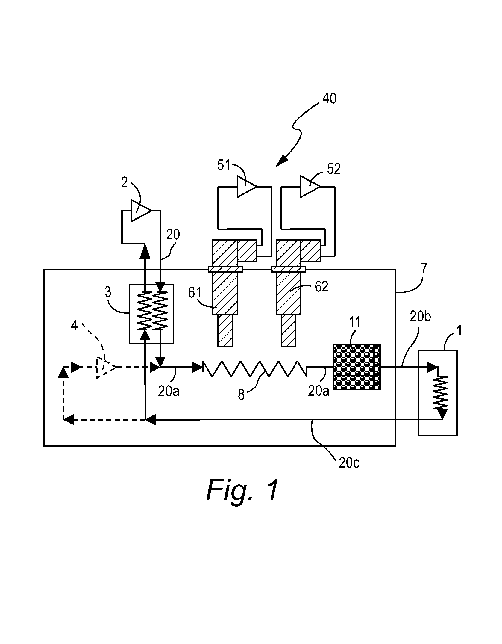
[0024]FIG. 1 is a schematic diagram of a cryogenic refrigeration system 40 for cooling thermal load 1. Thermal load 1 may be, for example, superconducting field winding coils of a rotor in a synchronous electric generator. While the exemplary embodiments below describe cryogenic refrigeration systems using a compressible gas as a cooling fluid, another cooling fluid such as a liquid may instead be used.

[0025]The refrigeration system 40 includes a heat exchanger 3 and a re-circulation device 2 such as a re-circulating compressor (when the cryogenic cooling fluid is a gas), fan or pump. While not shown in FIG. 1, a redundant (i.e., backup) re-circulation device can be connected in parallel with re-circulation device 2 to increase reliability. Re-circulation device 2 compresses and supplies warm temperature gas (e.g., 300°K) to heat exchanger 3. Re-circulation device 2 may include a storage container of cooling fluid. Heat exchanger 3 cools the gas received from re-circulation device 2...


PUM


Abstract

A cooling system for providing cryogenic cooling fluid to an apparatus comprises a re-circulation device, a passive cold storage device having a porous matrix of material which directly contacts the cryogenic cooling fluid as the cryogenic cooling fluid passes through the passive cold storage device, a first portion of a fluid communication feed line fluidly connecting the re-circulation device to the passive cold storage device, a second portion of a fluid communication feed line fluidly connecting the passive cold storage device to the apparatus for communicating cryogenic cooling fluid to the apparatus, and a fluid communication return line fluidly connecting the apparatus to the re-circulation device. The passive cold storage device may comprise a regenerative heat exchanger including a porous matrix of metal wire mesh, metal spheres or ceramic spheres.

Description

BACKGROUND OF INVENTION[0001]The present invention relates to a cryogenic refrigeration system for cooling a device such as a synchronous machine having a rotor with a high temperature superconducting component.SUMMARY OF INVENTION[0002]Cryogenic refrigerators are often used to cool a thermal load. Unfortunately, these cryogenic refrigerators (including their compressors) are subject to failures and therefore periodically require repair or replacement. During these periods of reduced refrigeration capacity, the temperature of cryogenic fluid (e.g., gas) circulated by the refrigerator temperature will rise unless the total thermal load on the refrigeration system is reduced to be smaller than the remaining refrigeration capacity. If the thermal load must continue to be cooled without reduction and the remaining refrigeration capacity is smaller than the thermal load, an additional source of cooling is needed until the full refrigeration capacity is restored.[0003]An example of a ther...

Claims


Application Information

Patent Timeline
Patent Type & Authority Patents(United States)
IPC IPC(8): F25D11/00F25B9/00F25B9/14F25B25/00F28D17/02
CPCF25B9/14F25B25/005F28D17/02F25B2400/24F25B2400/06
Inventor STEINBACH, ALBERT EUGENEACKERMANN, ROBERT ADOLPHHUANG, XIANRUI
Owner GENERAL ELECTRIC CO
Why Eureka
Try Eureka