
Method and apparatus for making a sorber

a sorbent and sorbent technology, applied in the field of sorbents, can solve the problems of relatively expensive drilling of sorbent holes, and achieve the effects of improving thermal path, increasing electrical field magnitude, and increasing electromagnetic wave penetration

Inactive Publication Date: 2006-02-28
ORACLE INT CORP
View PDF81 Cites 10 Cited by
  • Summary
  • Abstract
  • Description
  • Claims
  • Application Information

AI Technical Summary

Benefits of technology

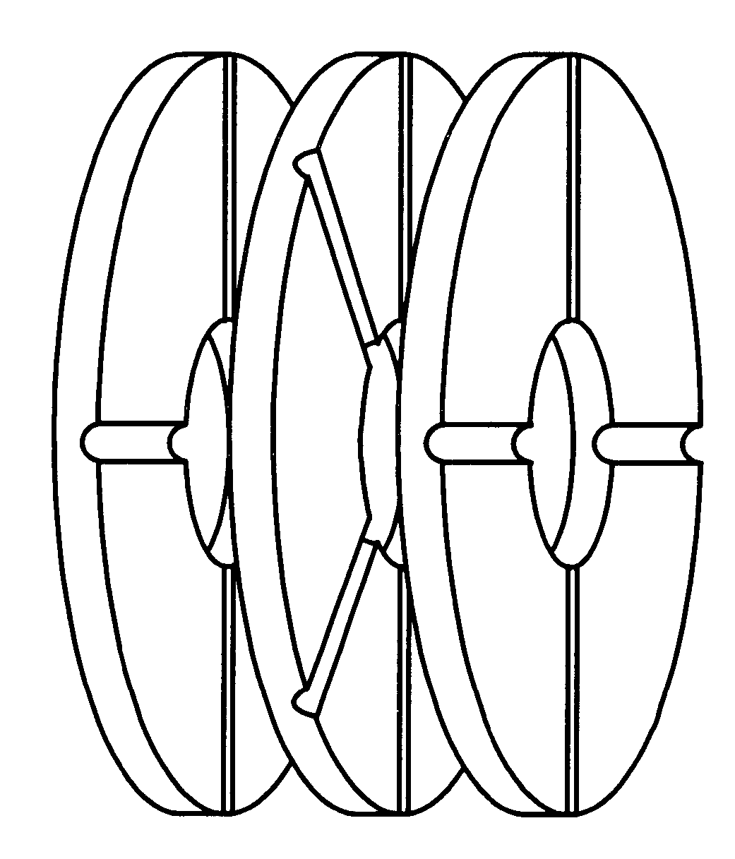
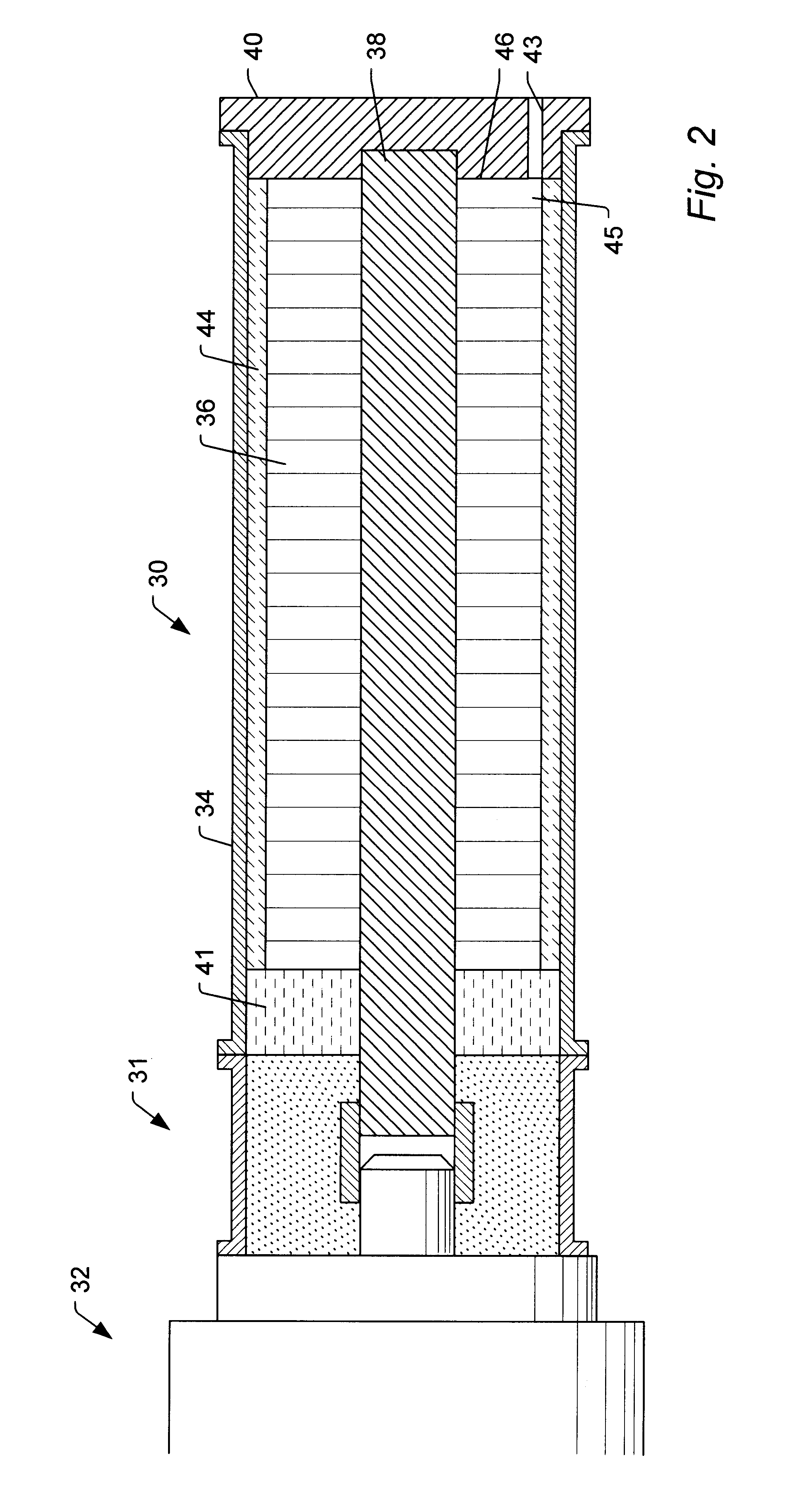
[0010]One embodiment of the present apparatus is a sorber for use in a sorption cooling system. The sorber comprises a cylindrical housing configured to enclose a sorbent mass. The sorbent mass itself comprises a plurality of disks of the sorbent material, wherein each disk has a plurality of radial grooves formed in the surface thereof. The disks are stacked so that the grooves form channels which extend from the outer surface of the sorbent mass to its interior. The disks can be tightly fitted to the housing to provide an improved thermal path between the sorbent and the exterior of the sorber.
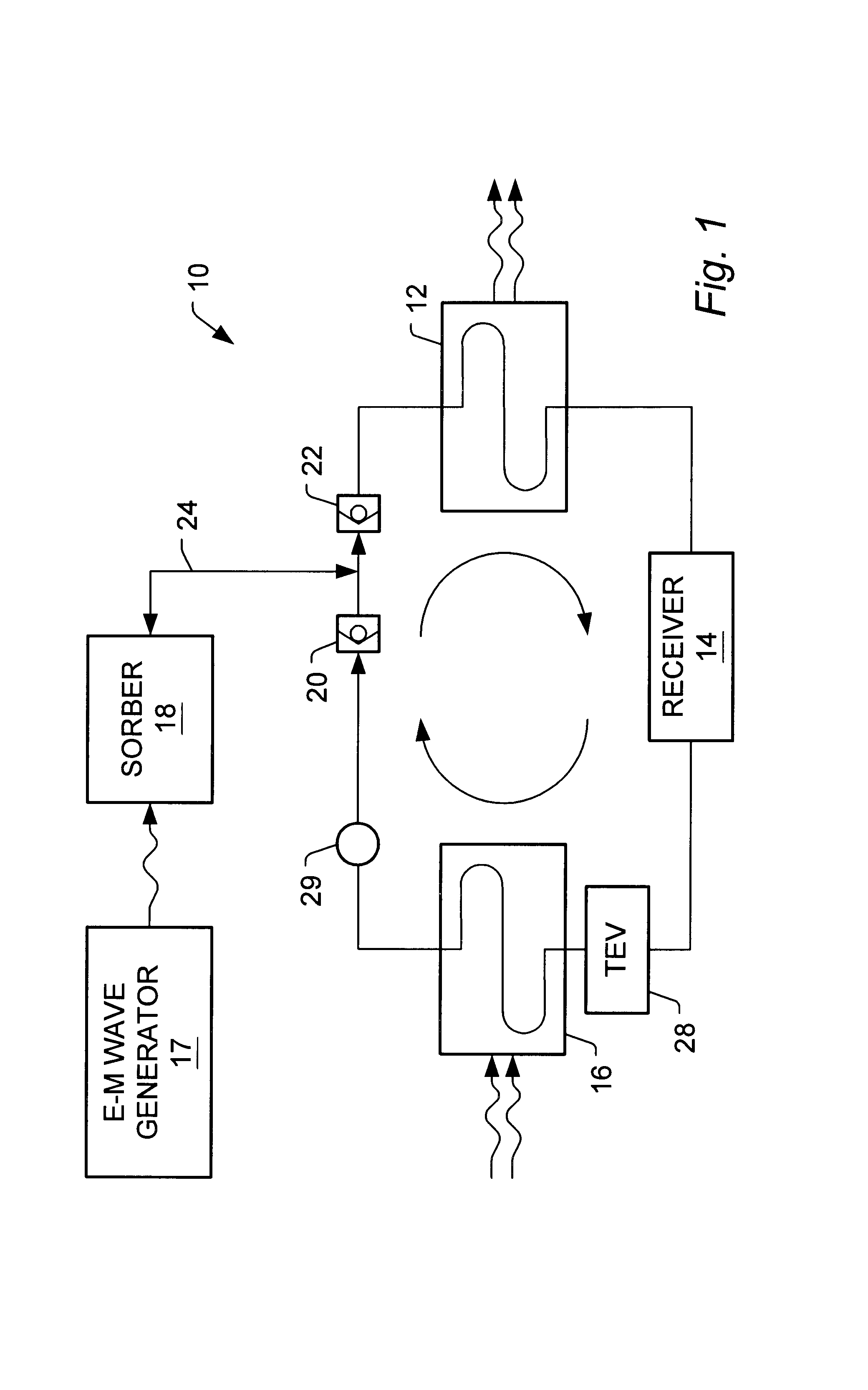
[0011]In one embodiment, the sorber is designed to be used in conjunction with an electromagnetic wave generator. The sorber has an inner conductor and an outer conductor which form a transmission line for electromagnetic waves produced by the generator. The electromagnetic waves are directed by the transmission line onto the sorbent material which lies between the inner and outer conductors. In order to increase the penetration of the electromagnetic waves into the sorbent and increase the magnitude of the electric field in the sorbent, metal disks are stacked alternately with the sorbent disks. Successive metal disks in the stack are sized to alternately contact the inner and outer conductors. The metal disks also serve to increase the thermal conductivity between the sorbent and the sorber's exterior.

Problems solved by technology

It can, however, be relatively costly to drill these holes in the sorbent.

Method used


Image

  • Method and apparatus for making a sorber
  • Method and apparatus for making a sorber
  • Method and apparatus for making a sorber

Examples


Embodiment Construction

[0026]One embodiment of the invention is described below. In this embodiment, a sorber for use in a sorption cooling system comprises a sorber enclosure and a sorbent mass contained therein. The sorbent mass itself consists of a set of disks stacked together face-to-face. The disks are manufactured from a sorbent material and are formed with grooves or other surface features which, when the disks are stacked, provide passageways through which a sorbate can be transported to the interior of the sorbent mass. The amount of surface area of the sorbent which is exposed to the sorbate is thereby increased, resulting in improved adsorption characteristics.

[0027]This disclosure is directed to a sorber structure which can be used in a variety of sorption systems. For the sake of simplicity, however, only a preferred embodiment is described in detail below. While the preferred embodiment described below is intended for use in a system that uses electromagmetic waves to desorb the sorbate fro...


PUM


Abstract

A structure and method of manufacture for a sorber, wherein a mass of sorbent contained in a sorber enclosure comprises a plurality of sorbent disks stacked in face-to-face relation. The sorbent disks are formed from a solid sorbent material such as zeolite and contain surface features in at least one face of each disk which, when the disks are stacked, form passageways by which sorbate is distributed throughout the mass of sorbent material. In one embodiment, each sorbent disk is annular in shape and has a plurality of radial grooves which extend from the periphery of the disk to the aperture through the center of the disk. The disks are stacked face-to-face and an inner conductor is inserted through the center apertures of the disks. This assembly is then inserted into a conductive housing and is enclosed by a pair of end plugs or caps which are secured to the housing. A port in one of the end caps allows sorbate to enter and exit the sorber enclosure. The sorber structure forms a coaxial transmission line for electromagnetic waves which are used to desorb sorbate from the sorbent disks. Alternate embodiments may use sorbent disks which employ surface features other than grooves to provide passageways through the sorbent mass. Alternate embodiments may also have configurations which are not cylindrical and / or coaxial.

Description

BACKGROUND OF THE INVENTION[0001]1. Field of the Invention[0002]The present invention relates to sorption systems where a sorbate is alternately adsorbed onto and desorbed from a sorbent and more particularly an improved sorber structure and method for making such a sorber.[0003]2. Description of Related Art[0004]In a sorption system, a first substance called a sorbate is alternately adsorbed (or absorbed) onto a second substance called a sorbent and then desorbed (or removed) from the sorbent. If the sorbate is adsorbed onto the sorbent, the system may be referred to as an adsorption system. If the sorbate is absorbed onto the sorbent, the system may be referred to as an absorption system. Sorption systems are often used to effectively compress the sorbate. For example, sorption systems may be used in refrigeration units in place of a compressor.[0005]During an adsorption reaction, the sorbate which is drawn onto the sorbent forms a sorbate / sorbent compound. In an absorption system...

Claims


Application Information

Patent Timeline
IPC IPC(8): F25B33/00F25B35/04
CPCF25B35/04
Inventor DAVIDSON, HOWARD
Owner ORACLE INT CORP
Learn More