Device for distributing substances

a technology for distributing devices and substances, applied in the direction of liquid bottling, packaging under special atmospheric conditions, infusion needles, etc., can solve the problems of user exposure to injury during handling, major risk of medium contamination, and time-consuming working steps of transfer, etc., to increase the safety of injuries during transport

Inactive Publication Date: 2006-02-28
HANSEN BERND
View PDF5 Cites 42 Cited by
  • Summary
  • Abstract
  • Description
  • Claims
  • Application Information

AI Technical Summary

Benefits of technology

[0004]Objects of the present invention are to provide a device which offers increased safety against injuries during transport, storage and use.
[0005]These objects are basically achieved in the present invention by a delivery device which has a protective cover which can be removed from the delivery container and which encloses the end of the hypodermic needle. Not only is the danger of unintentionally pushing back the safety body of the safety device avoided, but in addition increased protection against contamination is achieved.
[0006]If the outer end of the hypodermic needle is designed to penetrate the perforable closure of the container which holds the medium which is to be delivered, when the closure is punctured the safety body can be pushed back by contact with it out of its advanced protective position on the end of the hypodermic needle into the position of use. After the hypodermic needle is pulled out of the closure, the safety body can be pushed forward again into the protective position. In this embodiment handling is especially simplified.
[0008]As the safety body, the safety device can have an annular body movably guided on the section of the hypodermic needle projecting out of the closing unit. The annular body is connected to the closing unit by an elastic holding means which produces a holding force, is held by force-fit by the holding force of the holding means in the advanced protective position covering the end of the hypodermic needle, and can be pushed back against the holding force along the hypodermic needle into the position of use. The indicated annular body on its free face forms an annular broadened contact surface projecting on the forward point of the safety device radially over its other parts. By way of the widened contact surface, reliable contact behavior of the annular body with the puncturable point of the container on its removal opening results. Furthermore, as a result of the contact surface, when the perforable closure of the delivery container is punctured, the hypodermic needle cannot jam or be damaged on the sensitive tip.
[0010]Preferably, the support elements are rod-like plastic parts, are molded in one piece to the closing unit, and are divided by bending joints at approximately half the length. In this execution, the inherent elasticity of the material of the support elements makes it possible for the annular body to be advanced automatically again at least partially against the front end of the hypodermic needle after being pushed back into the position of use, for the annular body therefore to return automatically back into the protective position, or after using the device for it to be advanced simply slightly farther forward. Since the bending joints can completely fold down laterally, the rod-like plastic parts which form the respective bending joint are placed in contact on top of one another so that a high penetration depth of the hypodermic needle into the delivery container can be achieved. Also perforable closures with the corresponding thicknesses of the delivery container can thus be punctured in a controlled manner by the hypodermic needle.

Problems solved by technology

These working steps of transfer are on the one hand time-consuming, because the hypodermic needle and syringe must be unwrapped, the hypodermic needle mounted on the syringe, the vial opened or punctured and the syringe must be drawn up.
On the other hand, in these measures, a major risk exists of contamination of the medium.
Another problem in these delivery devices is the danger of injury to which the user is exposed during handling and which may be caused by the tip of the hypodermic needle.
The disadvantage in this known device is that there are no provisions against unintentional movement into the position of use, in which the end of the hypodermic needle projects exposed.
The known device can only be safeguarded after completed use by fitting the tip of the hypodermic needle in a receiving recess of the safety body after it has been advanced beyond the tip of the hypodermic needle after use of the device.
The known device is therefore unsatisfactory from the standpoint of safety.

Method used


Image

  • Device for distributing substances
  • Device for distributing substances
  • Device for distributing substances

Examples


Embodiment Construction

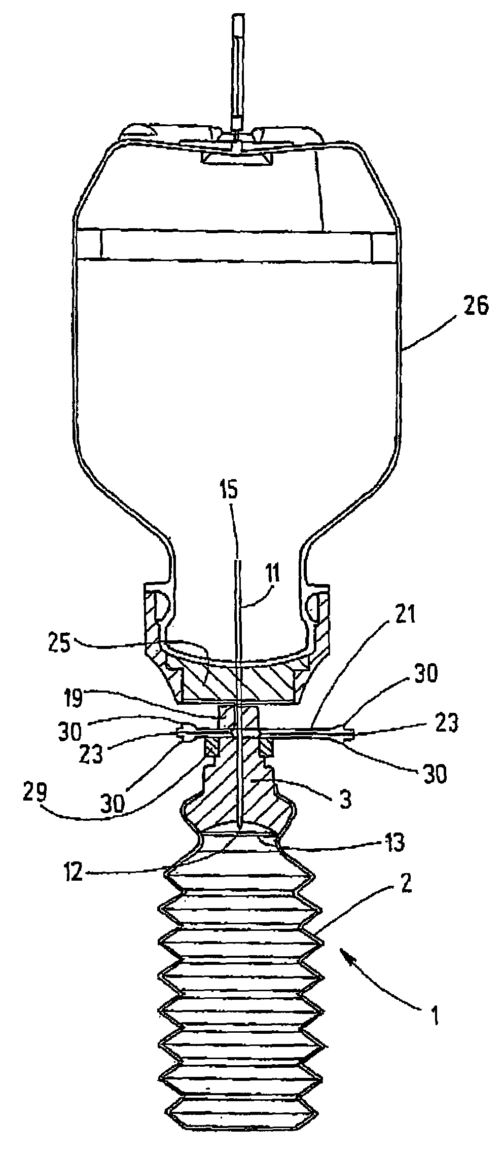
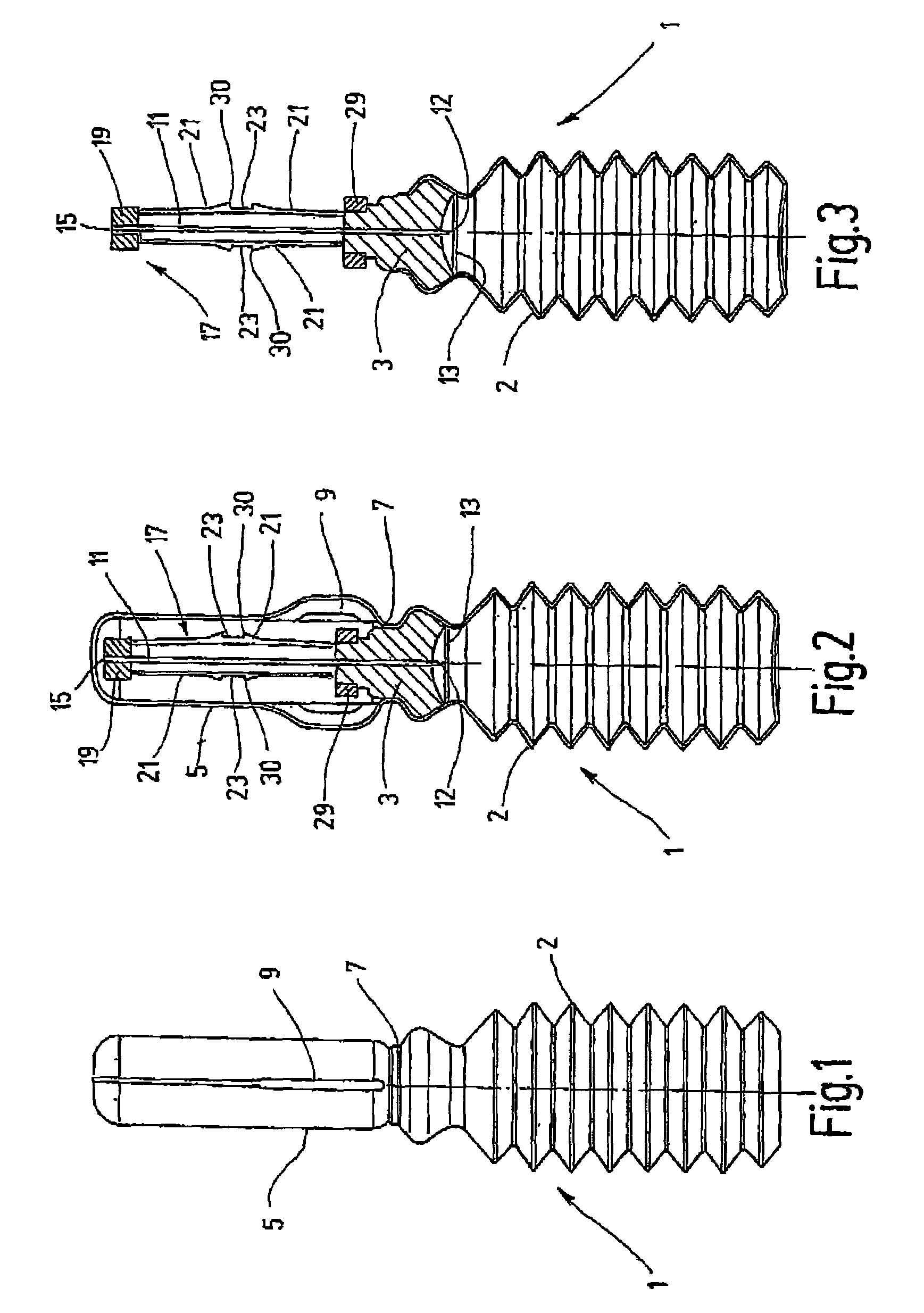
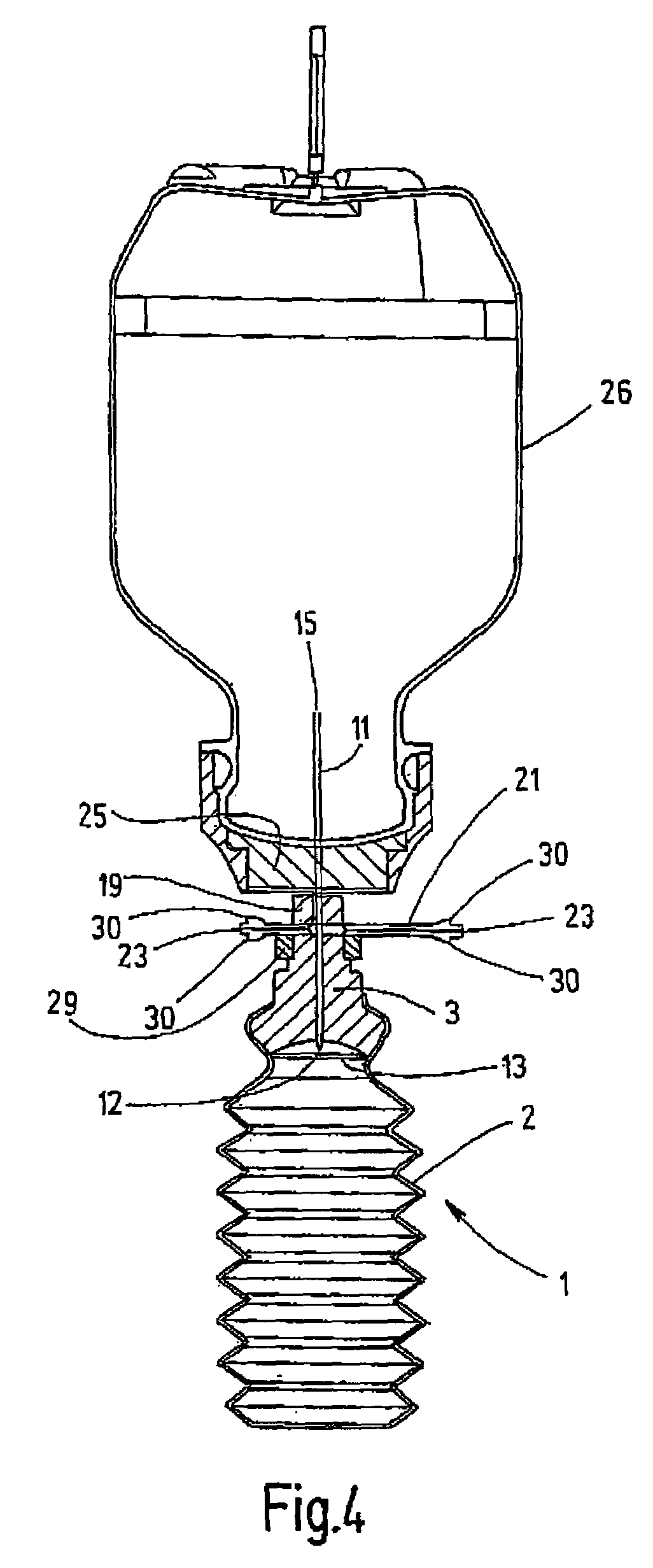
[0024]In the drawings, the delivery container is designated as a whole as 1. It is an ampule-like plastic container which has been produced using the known Bottelpack® process. The delivery container has a wall 2 provided with folds and made bellows-like, so that the delivery container 1 can be squeezed out from the configuration shown in FIGS. 1 to 4 to that shown in FIGS. 5 to 7. In the neck area, a closing unit 3 is inserted into the delivery container 1 as an insert part. Several components are molded onto the body of the closing unit which is molded from plastic. Among others, a safety device 17 is provided, which, before using the delivery device, is protected by a protective cover 5 molded on at a predetermined breakage point 7, see FIGS. 1 and 3, to the body of the delivery container 1. The cover has a laterally projecting finger-grip knob 9 which is used as purchase to twist the protective cover 5 off the delivery container 1 at the predetermined breakage point 7. FIG. 3 sh...


PUM

PropertyMeasurementUnit
lengthsaaaaaaaaaa
pressureaaaaaaaaaa
volumeaaaaaaaaaa

Abstract

A device for distributing substances includes distribution container (1) receiving a substance. The container has a closing unit (3) provided with a canula (11) for the substance to be distributed. The outer end (15) of the canula protrudes from the closing unit (3). A safety device (5, 17) can alternate between a protective state in which it covers the outer end (15) of the canula (11), and a user state for the distribution of the substance from the canula (11).

Description

FIELD OF THE INVENTION[0001]The present invention relates to a device for distributing substances. A primary, but not exclusive, application of the device involves delivering a desired volume of a medium, especially a liquid medium, into a receptacle. Preferably, the medium to be delivered is an additive which is introduced, for example, as an admixture of an active ingredient into a fluid located in the receptacle. The receptacle can be an infusion container with contents with which the medium is to be admixed as an additional active ingredient.BACKGROUND OF THE INVENTION[0002]For this purpose, the delivery device is conventionally a syringe with a hypodermic needle which punctures the perforable closure or plug of the receptacle, for example, an infusion container. After puncture, by pressing the syringe, the medium is injected into the receptacle. In this process the preparatory working step of filling the syringe is necessary, in which the desired amount of the medium from a sto...

Claims


Application Information

Patent Timeline
Patent Type & Authority Patents(United States)
IPC IPC(8): B65B1/04A61J3/00A61J1/00A61J1/20A61M5/28A61M5/32
CPCA61J1/2089A61M5/3275A61M5/282A61J1/067A61J2001/2013A61M2005/3247A61M5/3202A61J1/2013A61J1/201A61M5/28A61M5/24
Inventor HANSEN, BERND
Owner HANSEN BERND
Why Eureka
Try Eureka