Grinder cutter tooth and anvil assembly

a technology which is applied in the field of grinding cutter and anvil, can solve the problems of reducing the service life affecting the efficiency affecting the quality of the grinding cutter, so as to reduce the service time and the associated cost. , the effect of a longer tim

Inactive Publication Date: 2006-02-28
LANGLOIS MICHEL
View PDF9 Cites 30 Cited by
  • Summary
  • Abstract
  • Description
  • Claims
  • Application Information

AI Technical Summary

Benefits of technology

[0014]Advantages of the present invention include that the proposed grinder cutter tooth and grinder anvil, at least in part, overcome the aforementioned inadequacies of the prior art devices by allowing the same cutter tooth and the same anvil to be used for a greater length of time.
[0015]The proposed grinder tooth and anvil thus reduces both the service time and the costs associated with tooth and anvil replacement. Also, the proposed grinder cutter teeth and anvils are adapted to allow for optimization of the rotor cutting characteristics for a given power input to the grinder rotor.

Problems solved by technology

Although grinders have been in common use for an extended period of time, they nevertheless suffer from at least one main drawback.
Accordingly, they are subject to rapid wear and deterioration.
The deterioration of the teeth, in turn, leads to gradual loss of efficiency and may even potentially lead to break down of the grinder.
This, in turn, leads to relatively large operational costs.
Indeed, not only must the grinder be halted during replacement procedures but the teeth which are made out of a relatively strong material are quite expensive.
Because of the relatively high costs, in practice, the grinder teeth are seldom replaced with the required frequency to maintain good cutting characteristics.
The extensive time delays encountered in the resurfacing process are problematic and onerous.
In some instances, this may prove to be difficult.
For example, in situations wherein the grinders are portable and transported to various locations, maintaining a supply of extra cutting teeth may even prove to be impossible.
Although the teeth are subjected to greater compressive and impact forces than the anvils, the latter nevertheless eventually also suffer from wear and deterioration.
The deterioration of the anvil surfaces eventually leads to less than optimal rotor cutting characteristics for a given power input to the rotor.
Similarly to grinder teeth replacement, grinder anvil replacement requires lengthy and costly procedures.
Hence, the prior art seems to have failed in providing a satisfying solution to the problems associated with grinder teeth wear.
Furthermore, the prior art seems to have mostly neglected the possible contribution of the wear of grinder anvils to the loss of efficiency of the grinder machinery.

Method used


Image

  • Grinder cutter tooth and anvil assembly
  • Grinder cutter tooth and anvil assembly
  • Grinder cutter tooth and anvil assembly

Examples


Embodiment Construction

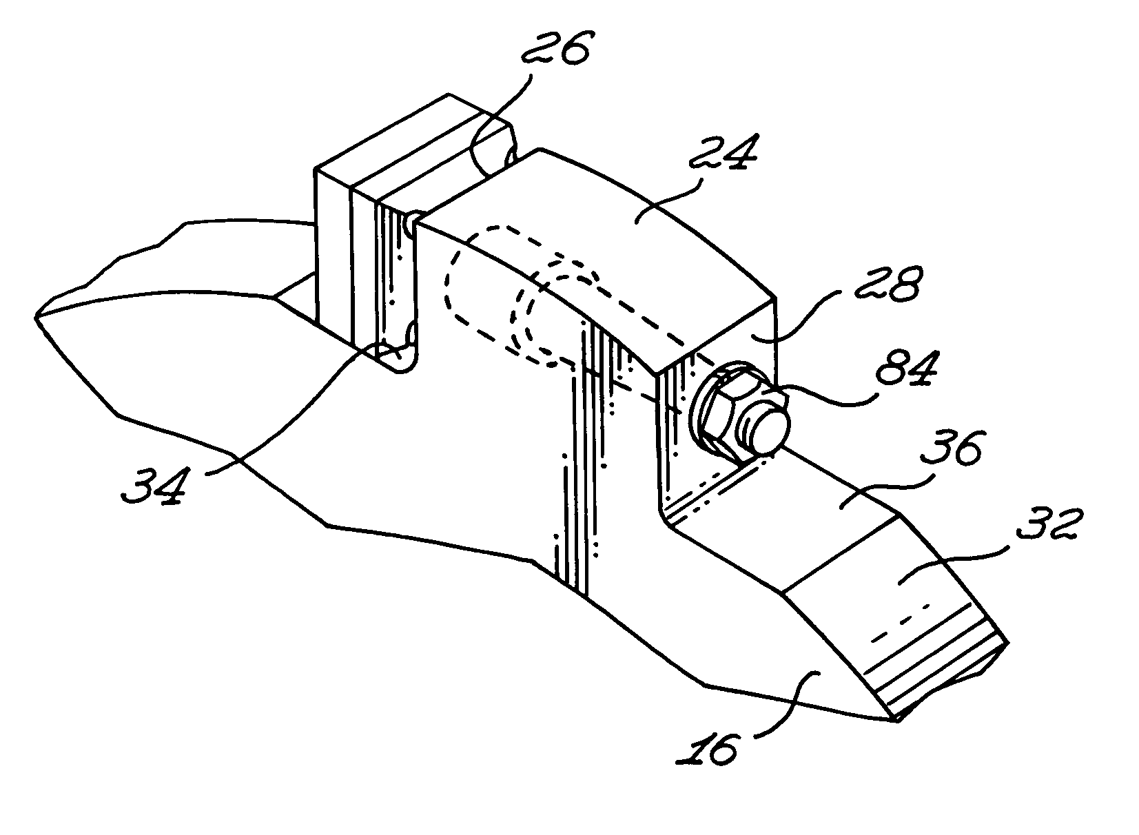
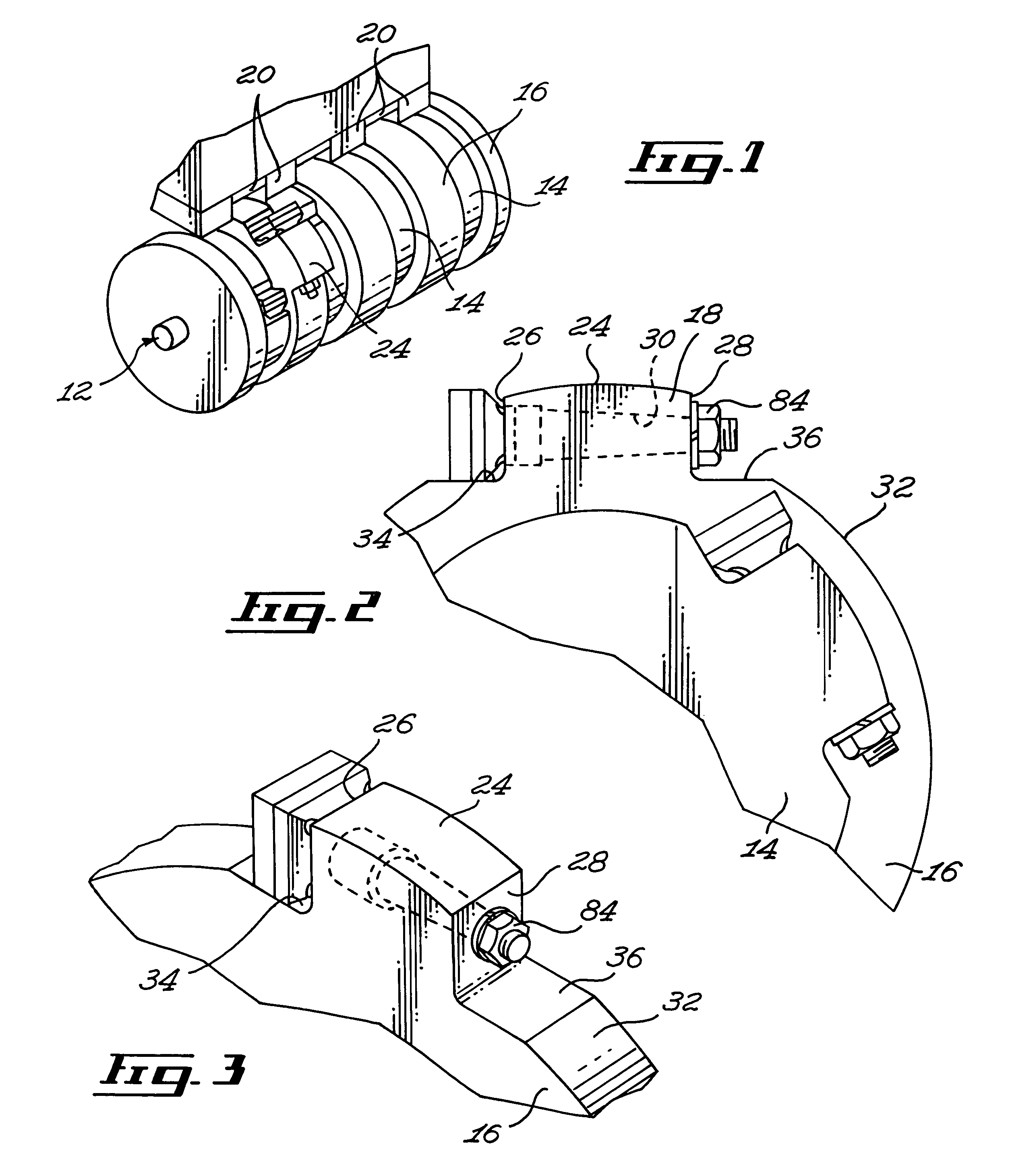
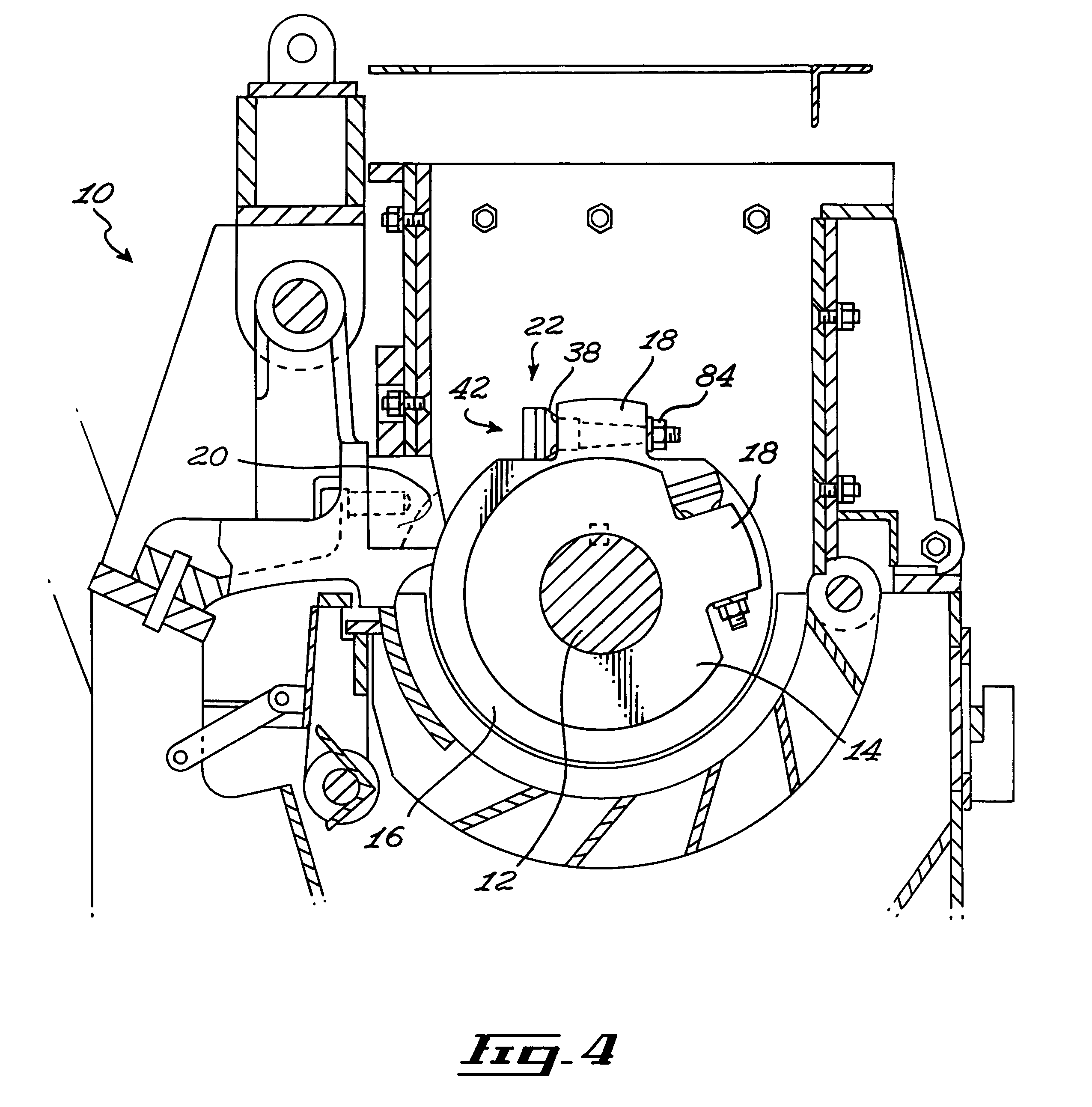
[0045]Referring to FIG. 4, there is shown a grinder 10 including a rotor 12 rotatable about the corresponding rotor axis. The rotor 12 includes a plurality of alternately small and large diameter breaker rings 14, 16. Each breaker ring 14, 16 carries at least one breaker head 18. In turn, a tooth assembly 22 is carried by each breaker head 18.

[0046]The tooth assemblies 22 and corresponding breaker heads are arranged to pass adjacent anvils 20. Typically, larger anvils 20 define relatively small spaces for the passage of the breaker heads 18 and teeth assemblies 22 of smaller diameter breaker rings 14 while smaller anvils 20 define larger spaces for the breaker heads 18 and teeth assembly 22 or larger breaker rings 16.

[0047]Typically, if desired, smaller diameter breaker rings 14 and their corresponding breaker heads 18 can be displaced inwardly of the outer periphery of larger diameter breaker rings 16 so that the larger anvils 20 protrude into the spaces between the larger diameter...


PUM


Abstract

A grinder tooth for use with a rotatable breaker ring part of a grinder, the breaker ring has a breaker head protruding radially from the ring outer peripheral surface for carrying the grinder tooth. The grinder tooth includes a blade holder, a shank extending from the blade holder and a blade releasably attached to the blade holder. The blade defines at least two grinding edges. The blade and holder are configured and sized so that the blade and holder peripheral surfaces are substantially in register with each other when the blade is attached to the holder. The blade and the holder are also configured and sized so that either one of the at least two grinding edges may be positioned radially outwardly by rotating the grinder tooth about the shank longitudinal axis allowing either one of the at least two grinding edges to be selectively used for grinding.

Description

FIELD OF THE INVENTION[0001]The present invention relates to the general field of grinder tools and is particularly concerned with a grinder cutter tooth and anvil assembly.BACKGROUND OF THE INVENTION[0002]Industrial grinders and shredders have become essential equipments in many processing and manufacturing facilities. These equipments are also commonly referred to as hammermills, pulverizer or hogs. Initially used mostly to grind bark removed from raw logs in sawmills and pulpmills, they are now widely used for the size reduction of a variety of materials including dry solids.[0003]Conventional grinders are frequently used for grinding raw logs which can then be burned as fuel or sold as horticultural mulch. The grinders are also typically used for grinding a wide range of other materials including tree stumps, slash from logging operations, land fill trash, soft metals such as aluminum and copper scraps, used automobile and light truck tires, construction dunnage and even some fo...

Claims


Application Information

Patent Timeline
Patent Type & Authority Patents(United States)
IPC IPC(8): B02C1/08B02C13/09B02C13/28B02C18/18
CPCB02C18/184
Inventor LANGLOIS, MICHEL
Owner LANGLOIS MICHEL
Why Eureka
Try Eureka