Valve seal assemblies and methods

a valve and seal assembly technology, applied in the field of valve seal assemblies, can solve the problems of special tools, expensive procedures, and seat installation or removal for repair purposes, and achieve the effects of reducing labor, improving seal assembly, and reducing the number of components of valve seal assembly

Active Publication Date: 2006-02-28
HP&T PROD
View PDF15 Cites 53 Cited by
  • Summary
  • Abstract
  • Description
  • Claims
  • Application Information

AI Technical Summary

Benefits of technology

[0014]Advantages of embodiments of the invention include providing an improved seal assembly for a valve engaging member. One of the seal rings between the pocket insert and the valve body pocket comprising a radial ring that retains the pocket insert within the valve body pocket, which reduces the number of components of the valve seal assembly, reduces labor, and reduces the cost of manufacturing. Fluid is prevented from entering between the pocket inserts and the valve body pockets, preventing erosion of the pockets of the valve body.

Problems solved by technology

With many of these, such as where the seats are press-fit into seat pockets in the valve body, the seats must be installed or removed for repair purposes using special tools and associated costly procedures.

Method used


Image

  • Valve seal assemblies and methods
  • Valve seal assemblies and methods
  • Valve seal assemblies and methods

Examples


Embodiment Construction

[0021]The making and using of the presently preferred embodiments are discussed in detail below. It should be appreciated, however, that the present invention provides many applicable inventive concepts that can be embodied in a wide variety of specific contexts. The specific embodiments discussed are merely illustrative of specific ways to make and use the invention, and do not limit the scope of the invention.

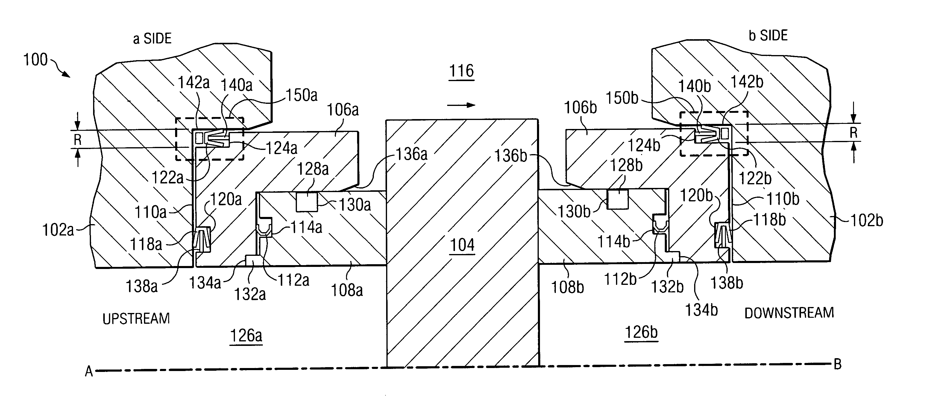
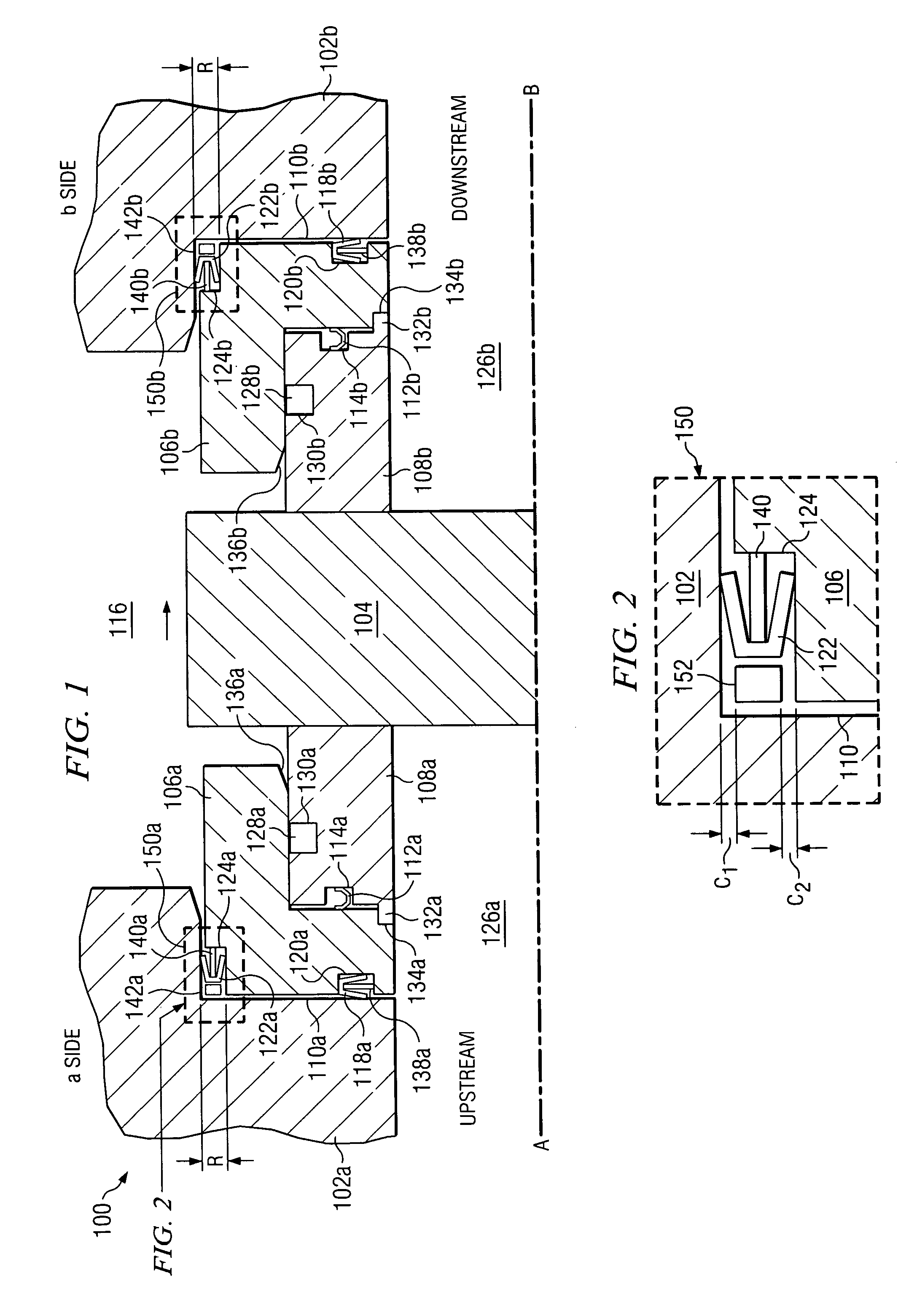
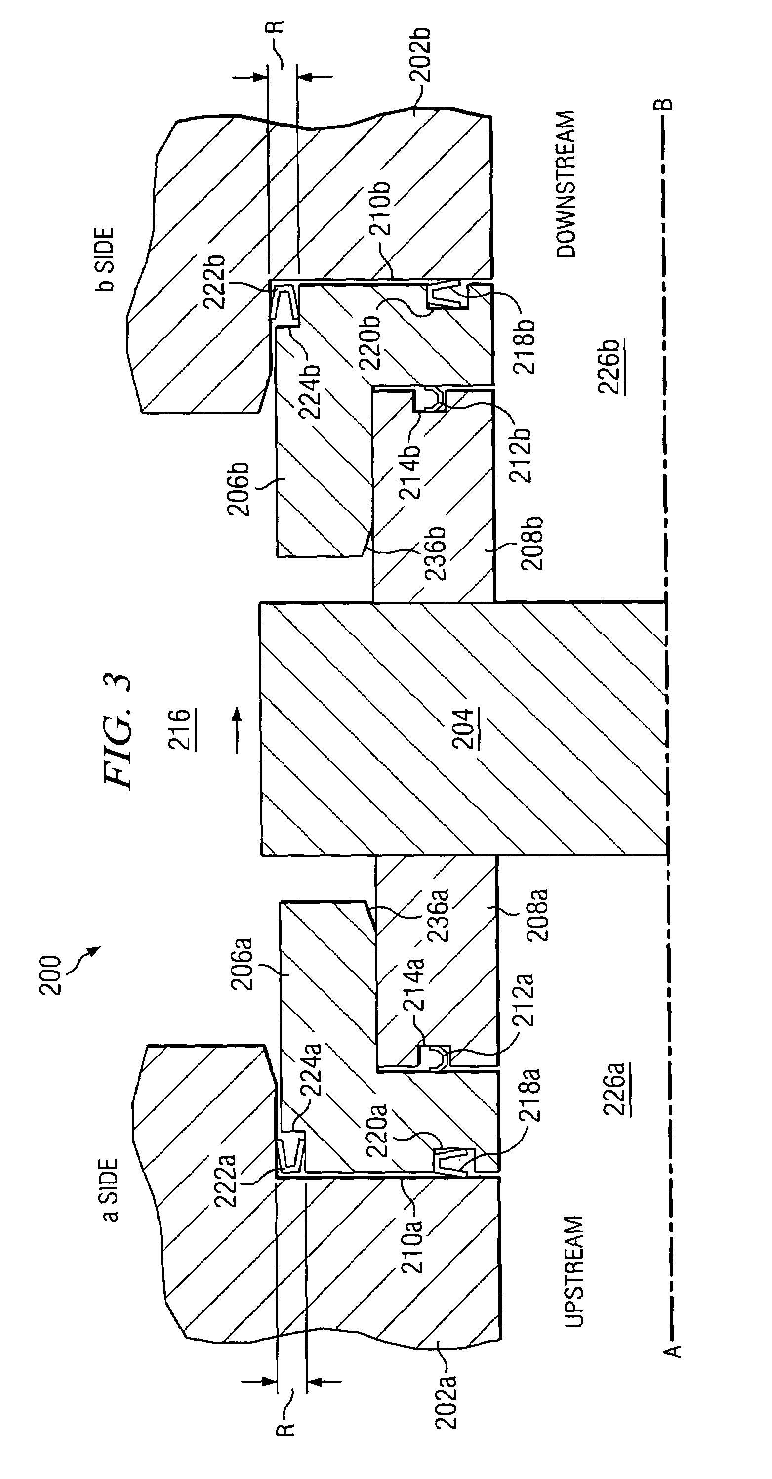
[0022]The present invention will be described with respect to preferred embodiments in a specific context, namely a valve sealing assembly for a gate valve. Embodiments of the present invention may also be applied, however, to other types of valve engaging members, for example. In the views shown in FIGS. 1 and 3, only half of the elements are shown; the elements shown are also disposed about a center-line A-B of the bore 126.

[0023]FIG. 1 illustrates a cross-sectional view of a preferred embodiment of the present invention, a valve seal assembly 100 having an upstream “a” sid...


PUM


Abstract

A method of sealing a valve engaging member to a valve body about a borehole and structure thereof. Two seal members disposed on either side of the valve engaging member include a seat member adjacent the valve engaging member and a pocket insert adjacent the seat member. The pocket inserts fit within first and second pockets of the valve body. A C-shaped seal ring is disposed between the seat member and pocket insert, and two U-shaped seal rings are disposed between the pocket insert and the valve body. One of the U-shaped seal rings between the pocket insert and the valve body functions both as a radial seal ring and a retaining ring.

Description

CROSS-REFERENCE TO RELATED APPLICATIONS[0001]This application relates to the following commonly assigned patent application: Ser. No. 09 / 911,148, filed on Jul. 23, 2001, entitled “Valve Seal Assemblies and Methods,” now U.S. Pat. No. 6,664,572, which application is hereby incorporated herein by reference.TECHNICAL FIELD[0002]The present invention relates generally to valves used in oilfield and, more particularly, to seal assemblies for valves and methods of sealing valves.BACKGROUND[0003]Various types of valves are used in oilfield well exploration, drilling, and production equipment. Valves are coupled to a pipeline and are typically used to shut off or turn on the flow of a fluid, such as a liquid, gas or both. Valves are typically either unidirectional or bi-directional. In a unidirectional valve, the valve has to be placed only in one unique way in a pipeline so as to match the pressure direction. In a bi-directional valve, either side of the valve can be used as the upstream s...

Claims


Application Information

Patent Timeline
Patent Type & Authority Patents(United States)
IPC IPC(8): F16K25/00F16K3/02
CPCF16K3/0227
Inventor CHATUFALE, VIJAY
Owner HP&T PROD
Why Eureka
Try Eureka