Rotary cutting tool

a cutting tool and rotary technology, applied in the field of rotary metal cutting tools, can solve the problems of affecting the use of the cutter head, the cutter head is hard to be removed from the reamer shank, and the union pin in particular is subject to great wear and tear

Active Publication Date: 2006-02-28
ISCAR LTD
View PDF27 Cites 55 Cited by
  • Summary
  • Abstract
  • Description
  • Claims
  • Application Information

AI Technical Summary

Problems solved by technology

However, this arrangement has the drawback that, particularly in the case of fairly strong feeding forces, the cutter head is pressed into the reamer shank and jams, especially because the conical engagement is also self-locking.
The cutter head is hard to remove from the reamer shank, whereby the union pin in particular is subjected to great wear and tear.
Furthermore, since the conical butt has an internal thread, the cutting head and conical butt cannot be made as a one piece integral member by form pressing and sintering a carbide powder.
To replace the cutter head the clamping bolt has to be disadvantageously completely removed from the reamer shank.
Moreover, when replacing a cutter head and tightening the clamping bolt to secure the cutter-head in position, there is no guarantee that the clamping bolt will end up in the same rotationally oriented position each time.
Therefore, even if the coolant were to be somehow supplied to the head of the bolt and radially directed coolant apertures were provided in the head of the bolt, it would not be certain that the apertures would aligned with the cutter-head cutting edges every time a cutter head was secured in position.
Furthermore, if instead of cutter blades secured to the cutter head, it was desired to form a one piece integral cutter head and shank from solid carbide, the elongated form of the cutter head together with the cutter-head shank makes it very difficult to form press and sinter.

Method used


Image

  • Rotary cutting tool
  • Rotary cutting tool
  • Rotary cutting tool

Examples


Embodiment Construction

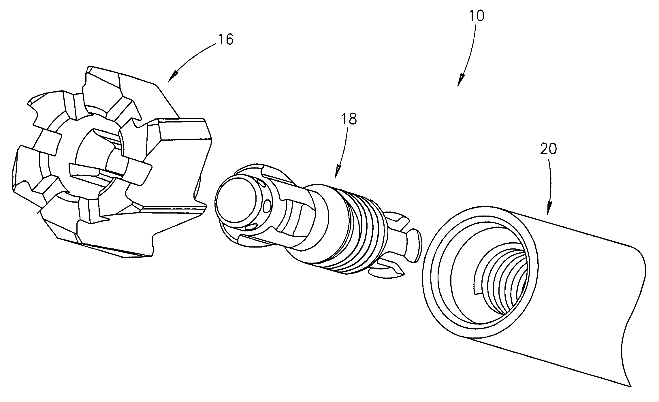
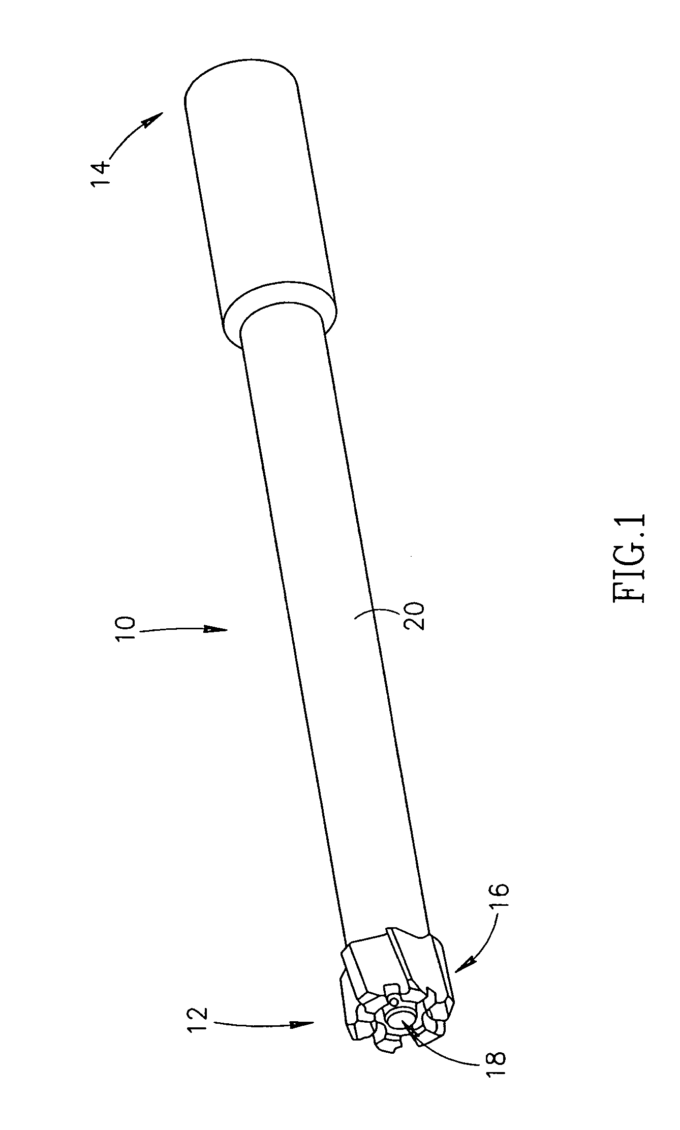
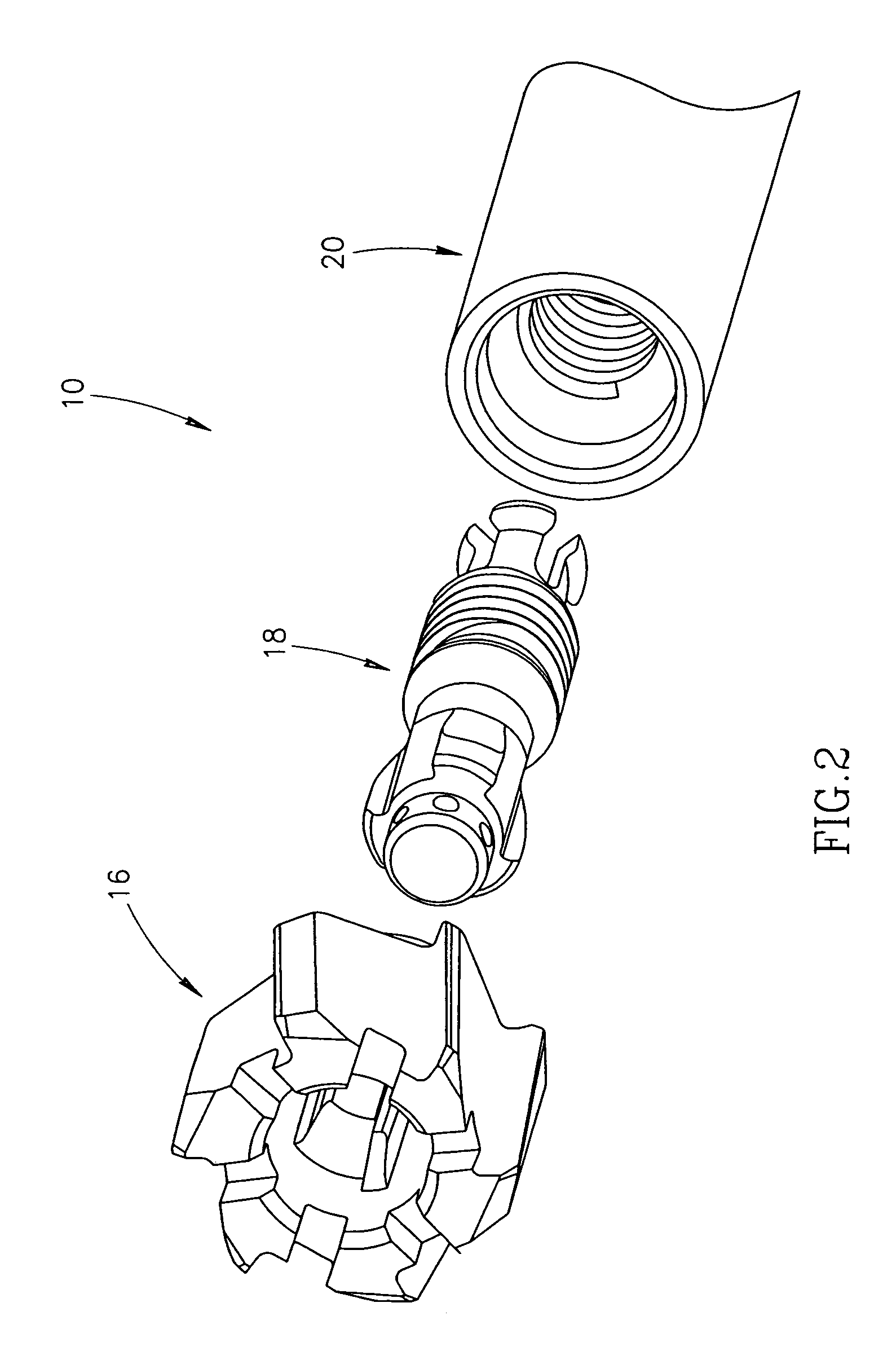
[0039]Attention is first drawn to FIGS. 1–3 showing a cutting tool in accordance with a first embodiment of the present invention illustrated by means of a reamer 10. The reamer 10 has a forward end 12, a rearward end 14 and a longitudinal axis of rotation A passing through the forward and rearward ends 12,14 defining a forward to rearward direction. The reamer 10 comprises a cutting head 16, a screw member 18, and a tool shank 20. The cutting head 16 preferably is a form pressed and sintered hard metal body made from a carbide powder such as Tungsten Carbide. The screw member 18 and the tool shank 20 are formed of machined steel or other hard materials. The tool shank 20 has an axially directed coolant channel 22 for providing coolant to the cutting head 16.

[0040]The cutting head 16, shown in FIGS. 4–6, has a forward end 24, a rearward end 26, an axis of rotational symmetry B, and an axially directed cutting head bore 27 having a bore surface 28. When securing the cutting head 16 t...


PUM

PropertyMeasurementUnit
resilientaaaaaaaaaa
feeding forcesaaaaaaaaaa
rotationaaaaaaaaaa

Abstract

A rotary cutting tool has a cutting head, a screw member and a tool shank. The cutting head has an axially directed through bore with locking wings protruding from the bore surface. Each locking wing having a sloping locking surface and stopper with a stop surface. The screw member has outwardly radially protruding clamping wings each having a sloping clamping surface, and an associated side abutment surface. The screw member is in threaded engagement with the tool shank, with the clamping wings and locking wings aligned in pairs with the locking and clamping surfaces of each pair in abutment, and with each stop surface in abutment with a given side abutment surface.

Description

FIELD OF THE INVENTION[0001]The present invention relates in general to rotary metal cutting tools, and specifically to reamers having replaceable cutting heads.BACKGROUND OF THE INVENTION[0002]A reamer of this type is disclosed in U.S. Pat. No. 4,040,765. In this design the reamer has an interchangeable cutter head with a conical butt which is inserted in a matching conical socket in the reamer shank. The cutter head is screwed to the reamer shank via a screw bolt. The conical engagement between the cutter head and the reamer shank ensures a connection free from play. However, this arrangement has the drawback that, particularly in the case of fairly strong feeding forces, the cutter head is pressed into the reamer shank and jams, especially because the conical engagement is also self-locking. The cutter head is hard to remove from the reamer shank, whereby the union pin in particular is subjected to great wear and tear. In this reamer there is no provision for equipping the cutter...

Claims


Application Information

Patent Timeline
Patent Type & Authority Patents(United States)
IPC IPC(8): B23B51/00B23B31/00B23C5/26B23B31/02B23B31/11B23B31/20B23C5/10B23C5/28B23D77/00
CPCB23B31/008B23B31/11B23C5/10B23C5/28B23D77/00B23B2231/0204Y10T408/9098Y10T408/90993Y10T279/17888Y10T279/16Y10T408/95B23C2210/03
Inventor HECHT
Owner ISCAR LTD
Why Eureka
Try Eureka