Fastening device

a technology of fastening device and clamping area, which is applied in the direction of buckles, transportation and packaging, transportation items, etc., can solve the problems of difficult operation of pulling up the base b>17/b> to loosen the first rope b>20/b>, poor quality of attachment poor quality of fastening device, so as to improve the frictional resistance of the first rope, increase the clamping area, and smooth the effect of the passage rop

Active Publication Date: 2006-02-28
GOOD SUCCESS CORP
View PDF15 Cites 20 Cited by
  • Summary
  • Abstract
  • Description
  • Claims
  • Application Information

AI Technical Summary

Benefits of technology

[0011]In a more preferred embodiment, the three cross bars are provided with roughened outer surfaces to enhance frictional resistance against the rope, and the third cross bar is provided with a concave portion for increasing the clamping area for the rope and a convex portion for smoother passage of the rope.

Problems solved by technology

First of all, because the first rope 20 only goes around the second cross plate 16 and then around the first cross plate 15, in addition to the smoothness of the surface of the two cross plates 15,16, there is not much frictional resistance provided relative to the first rope 20. Thus, when force is applied to pull the second section 202 of the first rope 20 in a direction opposite to the second rope 21, undesirable sliding movement of the first rope 20 could very well occur, leading to the drawback of poor quality of attachment of the first rope 20 to the fastening device.
Secondly, because after the first rope 20 is fastened to the fastening device, the first section 201 thereof is often in tight contact with the base 17, this causes the drawback that the operation of pulling up the base 17 to loosen the first rope 20 is not easy.

Method used


Image

  • Fastening device
  • Fastening device
  • Fastening device

Examples


Embodiment Construction

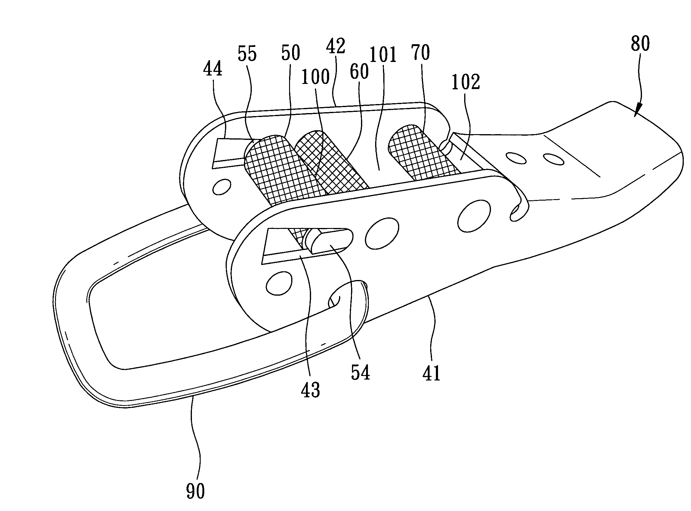
[0021]The construction of a preferred embodiment of the fastening device according to the present invention will now be described in greater detail below. It should be noted that the terms used in the entire text herein to indicate the relative position, such as “upward,”“downward” and “underneath,” are based on the normal operating position of the fastening device as shown in FIGS. 3, 4 and 5.

[0022]As shown in FIGS. 3, 4 and 5, the fastening device according to the present invention is used to fix an object 110 (as that shown in FIG. 8) with a first rope 30 and a second rope 31 that are inserted therethrough and fastened thereto. The preferred embodiment as shown comprises a main body which includes a base 80, two spaced-apart legs 41,42 extending longitudinally from the base 80 and each having one end 411,421 distal from the base 80, and a first cross bar 70, a second cross bar 60 and a third cross bar 50 interposed between the two legs 41,42; and a ring member 90 pivotally mounte...


PUM


Abstract

A fastening device for fastening a rope comprises a main body which includes a base, two spaced-apart legs extending longitudinally from the base and each having one end extending away from the base, and a first cross bar, a second cross bar and a third cross bar spaced from one another and disposed transversely between the two legs in that order from the base to the ends of the legs. The third cross bar is movable to a first position proximate the second cross bar or to second position distal from the second cross bar. First, second and third spaces are defined by the third cross bar with the second cross bar, the second cross bar with the first cross bar, and the first cross bar with the base, respectively, for passage of the rope. A ring member is pivotally mounted in the ends of the legs.

Description

BACKGROUND OF THE INVENTION[0001]1. Field of the Invention[0002]The present invention relates to a fastening device for fastening a rope, more particularly to a fastening device of the type in which a pair of ropes can be attached for securing an object or article.[0003]2. Description of the Related Art[0004]Generally, when transporting automobiles from a source to a destination by cargo vessels, a fastening device is used to fasten two ropes which are connected respectively to an automobile and the deck of the ship, the two ropes being threaded through and fastened in the fastening device. The fastening device with the ropes is usually provided between the automobile and the ship body, and the two ropes are attached to both the automobile and the ship body so as to position the automobile in place. As shown in FIGS. 1 and 2, the conventional fastening device 10 includes a base 17 and two spaced apart webs 11,12 extending longitudinally from the base 17; a first cross plate 15 and a...

Claims


Application Information

Patent Timeline
Patent Type & Authority Patents(United States)
IPC IPC(8): A44B11/00B60P3/06
CPCA44B11/125B60P7/0823B60P3/079
Inventor WEN-HSIANG, HSIEH
Owner GOOD SUCCESS CORP
Why Eureka
Try Eureka