Device for controlling variable-pitch vanes in a turbomachine

a variable-pitch vanes and turbomachine technology, applied in the field of turbomachines, can solve problems such as impede efficiency optimization and fuel saving, and achieve the effects of simple, effective and inexpensiv

Active Publication Date: 2006-02-28
SN DETUDE & DE CONSTR DE MOTEURS DAVIATION S N E C M A
View PDF3 Cites 17 Cited by
  • Summary
  • Abstract
  • Description
  • Claims
  • Application Information

AI Technical Summary

Benefits of technology

[0007]A particular object of the present invention is to provide a solution to this problem that is simple, effective, and inexpensive.
[0009]By means of this configuration, the points of rotation of the links are situated in the contact zones between the links and the radial fingers, and no longer in the contact zones between the radial fingers and their cylindrical housings, thereby guaranteeing that angular displacement of the ring leads to the same amount of turning for all of the vanes in the row.
[0011]This makes it possible to reduce the stresses and deformations of the links while adjusting the angular pitch of the vanes.
[0014]This configuration leads to a saving in weight since it enables the above-mentioned angled tabs to be omitted together with their screws for fastening them to the semicircular elements and the bridges of the control ring.

Problems solved by technology

This different adjustment of the vanes connected to the bridges impedes optimization of efficiency and fuel saving.

Method used


Image

  • Device for controlling variable-pitch vanes in a turbomachine
  • Device for controlling variable-pitch vanes in a turbomachine
  • Device for controlling variable-pitch vanes in a turbomachine

Examples


Embodiment Construction

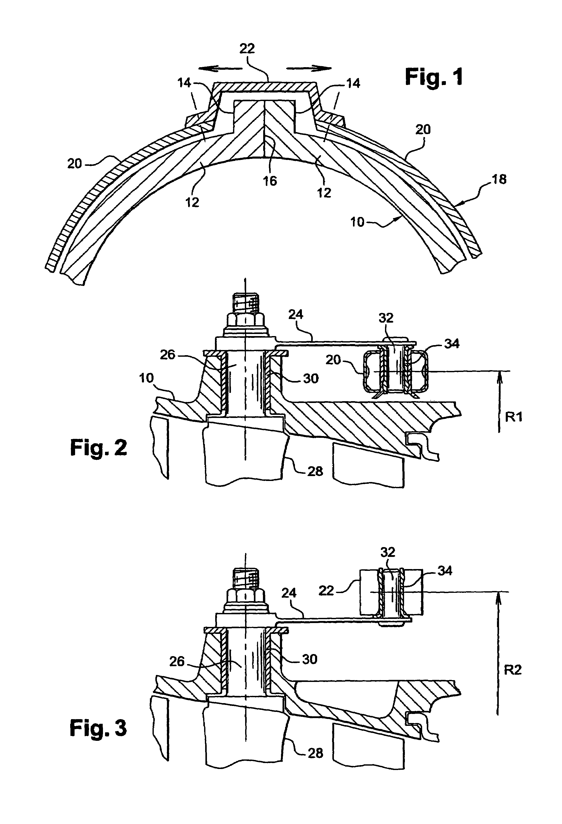
[0025]FIG. 1 is a highly diagrammatic cross-section view showing a portion of a turbomachine casing 10, said casing being made up of two half-shells 12 having longitudinal assembly flanges 14 pressed against each other along a junction plane 16 and projecting outwards from the casing 10.

[0026]A ring 18 for controlling the angular position of variable-pitch vanes surrounds the outside of the casing 10 in the immediate vicinity thereof, and is made up of two approximately semicircular elements which are rigidly interconnected at their ends by two bridges 22, only one of which is shown in FIG. 1, each bridge being placed astride the longitudinal flanges 14 of the casing 10 and allowing the ring 18 to turn to a certain extent about its longitudinal axis, which coincides substantially with the longitudinal axis of the casing 10.

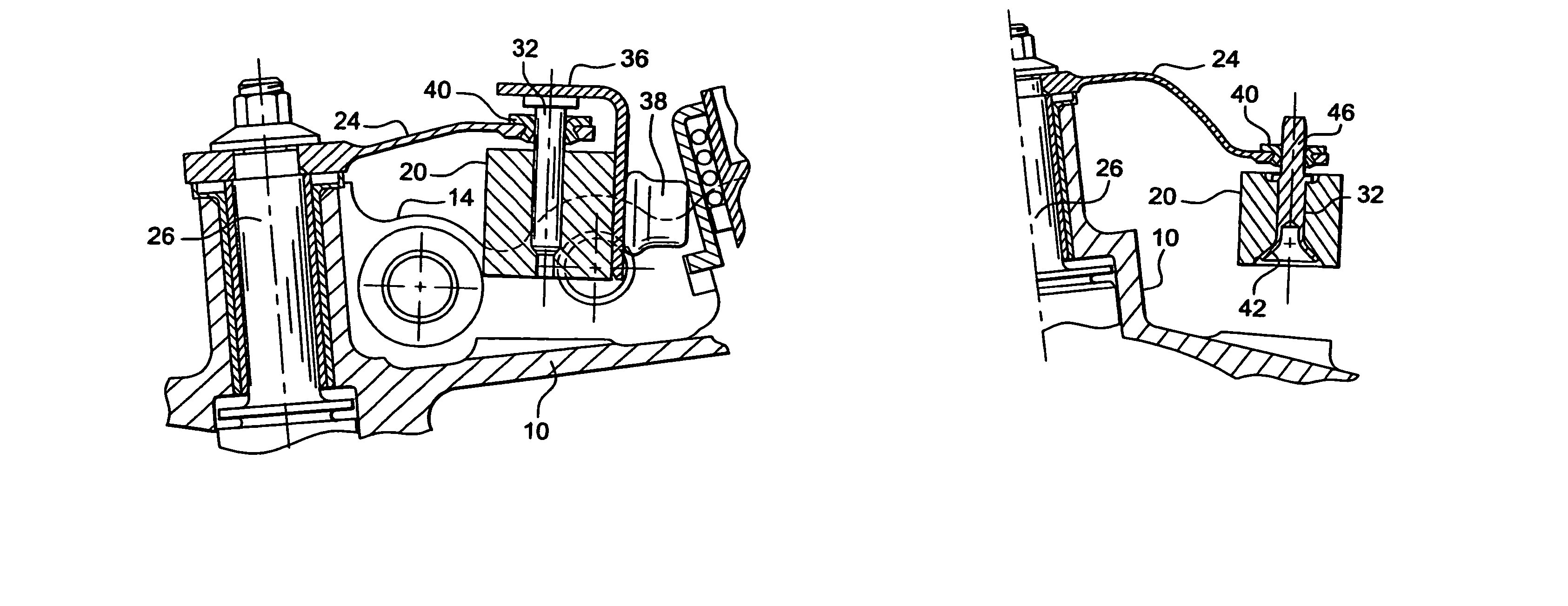
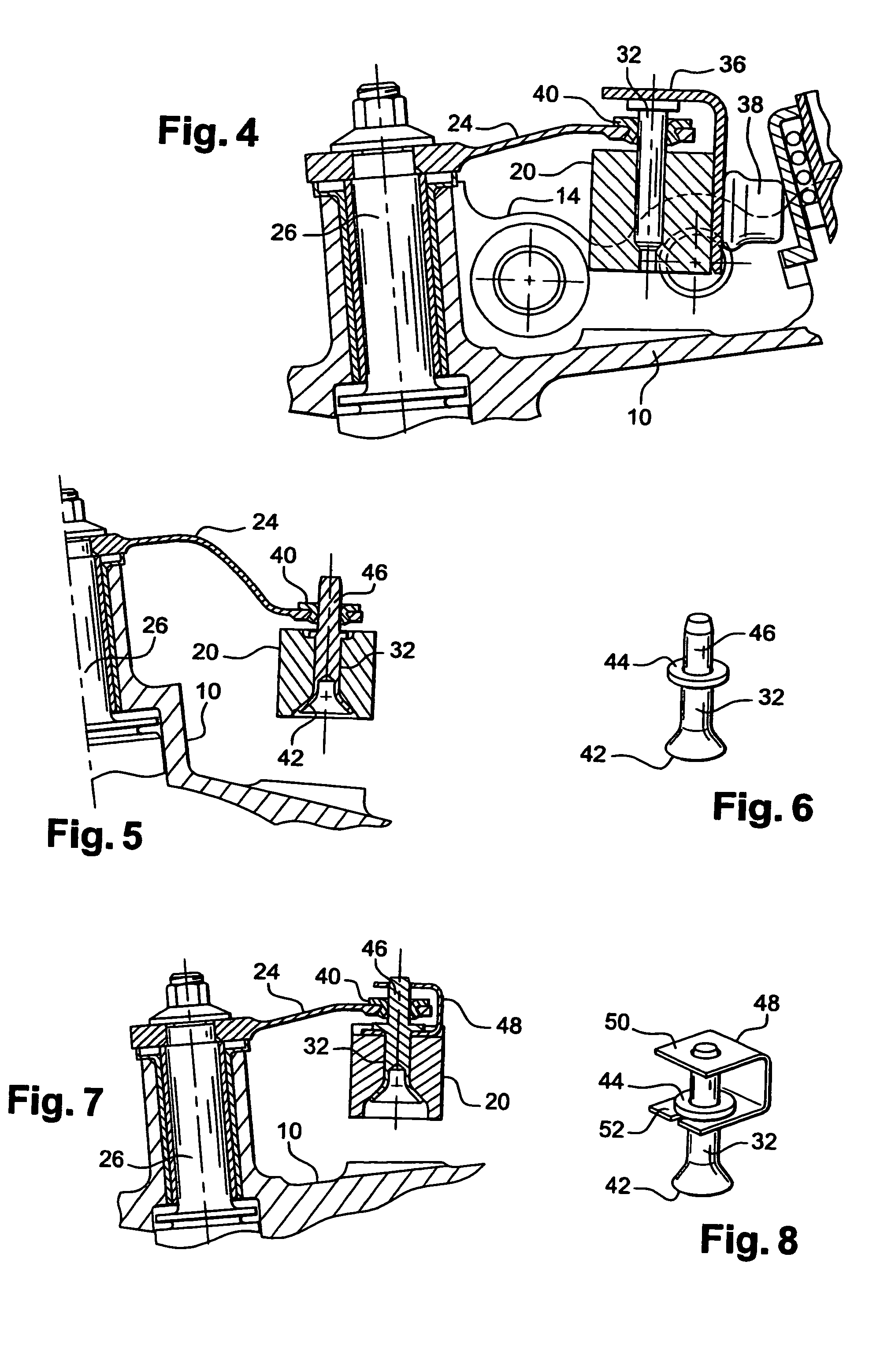
[0027]The means connecting the control ring to a row of variable-pitch vanes are shown diagrammatically in FIGS. 2 and 3.

[0028]These means comprise links 24, each...


PUM


Abstract

A device for controlling variable-pitch vanes in a turbomachine comprises links connecting the radial pivots of the vanes to radial fingers carried by semicircular elements and bridges of a control ring, the links being mounted in ball-and-socket manner on the radial fingers which are fixed to the control ring. This form of mounting enables all the vanes associated with the control ring to be set to the same angular pitch.

Description

[0001]The invention relates to a device for controlling variable-pitch vanes in a turbomachine, such as an airplane turboprop or turbojet engine, in particular.BACKGROUND OF THE INVENTION[0002]In such a turbomachine, the purpose of adjusting the angular position or “pitch” of certain stator vanes is to optimize the efficiency of the turbomachine and to reduce its fuel consumption under differing flight configurations. Such adjustment is generally performed for one or more rows of vanes by means of a control ring which surrounds the outside of the turbomachine stator and which can be turned about the longitudinal axis of the stator by drive means such as an actuator or an electric motor. Turning movement of the ring is transmitted by links to the vanes of the row, each link being secured at one of its ends to a vane and carrying a radial finger at its other end, which finger is engaged in a cylindrical housing in the control ring.[0003]In turbomachines presenting a certain power leve...

Claims


Application Information

Patent Timeline
Patent Type & Authority Patents(United States)
IPC IPC(8): F01D17/16F01D17/14F01D1/00F04D29/56
CPCF01D17/162Y02T50/671Y02T50/60
Inventor RAULIN, DOMINIQUEMAROIS, FABRICECHATEL, ALAINBOURON, ALAIN
Owner SN DETUDE & DE CONSTR DE MOTEURS DAVIATION S N E C M A
Why Eureka
Try Eureka