
Finite amplitude distortion-based inhomogeneous pulse echo ultrasonic imaging

a pulse echo and ultrasonic imaging technology, applied in the field of ultrasonic pulse echo imaging, can solve the problems of inhomogeneous media with significant lateral and contrast resolution loss, increase in the width of the main beam, and increase in the side lobe level, so as to improve the ultrasonic imaging and methods

Inactive Publication Date: 2006-02-28
RES CORP TECH INC
View PDF40 Cites 15 Cited by
  • Summary
  • Abstract
  • Description
  • Claims
  • Application Information

AI Technical Summary

Benefits of technology

"The present invention is a method and system for improving ultrasonic imaging and methods. It involves using the enhanced inhomogeneous focusing properties of the finite amplitude distortion generated higher harmonics of an ultrasonic imaging beam to obtain improved contrast resolution and lateral resolution images. The method includes generating an ultrasonic signal, directing it into a sample, and processing the received distorted signal to form an image. The resulting image is based on one of the received finite amplitude distortion component (or nonlinearly-generated higher harmonics) associated with the transmitted signal. The invention can provide better image quality and more accurate information about the sample being imaged."

Problems solved by technology

For example, ultrasonic pulse echo imaging in inhomogeneous media suffers from significant lateral and contrast resolution losses due to the defocusing effects of the inhomogeneities of the media.
The losses in lateral and contrast resolution are associated with increases in the width of the main beams and increases in side lobe levels, respectively.
These two forms of resolution loss represent a significant hurdle to improving the clinical utility of biomedical ultrasonic imaging.

Method used


Image

  • Finite amplitude distortion-based inhomogeneous pulse echo ultrasonic imaging
  • Finite amplitude distortion-based inhomogeneous pulse echo ultrasonic imaging
  • Finite amplitude distortion-based inhomogeneous pulse echo ultrasonic imaging

Examples


Embodiment Construction

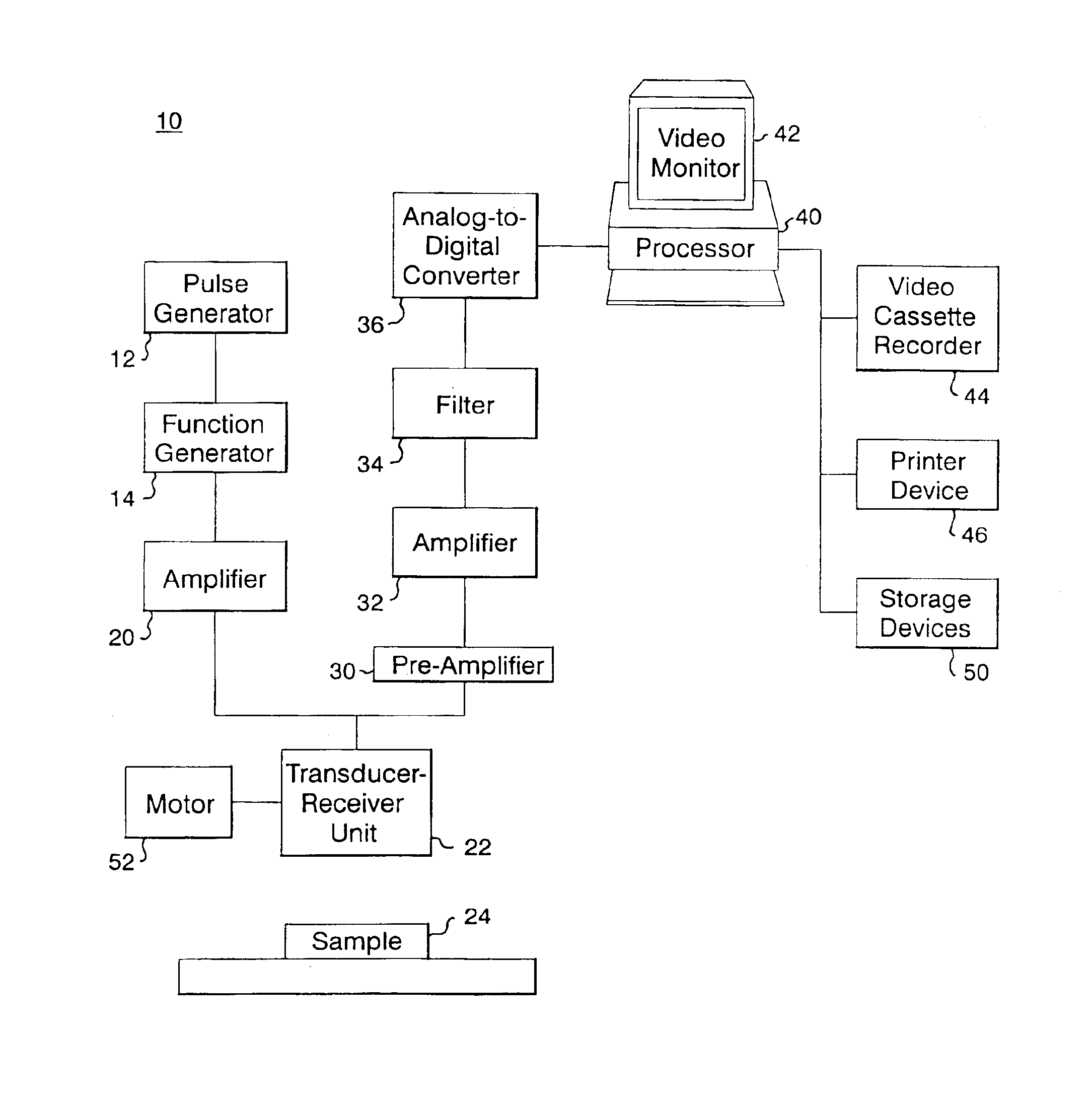
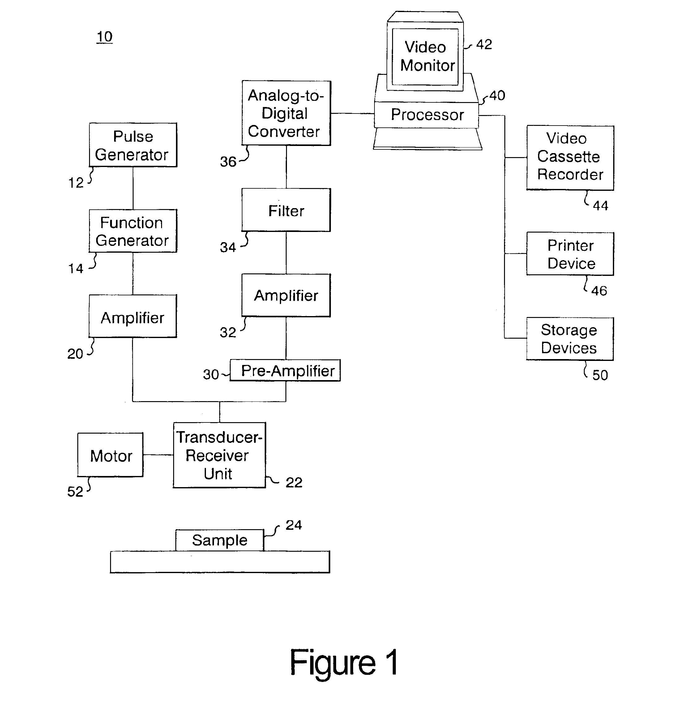
[0035]FIG. 1 illustrates ultrasonic imaging system 10. A pulse generator 12 and a function generator 14 produce a sinusoidal pulse ultrasonic signal of, for example, 2.0 MHz at a pulse repeat frequency of, for instance, 1 kHz. This signal is sent to amplifier 20, which amplifies the signal and transmits the amplified signal to transducer-receiver unit 22, and this unit then transmits the signal into sample 24.

[0036]In this sample 24, the input signal is both distorted and reflected. The distortion creates a distorted signal having a multitude of component signals, each of which has a respective frequency or frequency bandwidth. The distorted signal is reflected by sample 24, and this reflected signal is received by transducer-receiver unit 22, amplified by pre-amplifier 30, and then further amplified by amplifier 32. The received and amplified signal is then sent through a high-pass filter 34 to enhance the relative strength of the desired higher harmonic component of the received s...


PUM


Abstract

A method and system for imaging a sample. The method includes the steps of generating an ultrasonic signal, directing the signal into a sample, which signal is distorted and contains a first order and higher order component signals at first and higher frequencies respectively. The received distorted signal is processed, and an image is formed, and then displayed, from one of the higher order component signals of the received distorted signal.

Description

CROSS REFERENCE OF RELATED APPLICATIONS[0001]This application is a continuation of application U.S. Ser. No. 08 / 746,360, filed Nov. 8, 1996.BACKGROUND OF THE INVENTION[0002]This invention generally relates to ultrasonic pulse echo imaging, and more specifically, to ultrasonic pulse echo imaging based on the distortion of ultrasonic signals transmitted into samples.[0003]Ultrasonic pulse echo imaging is widely used in many medical applications. While this technique has received wide acceptance, it would be desirable to improve the resolution of the images formed from this technique. For example, ultrasonic pulse echo imaging in inhomogeneous media suffers from significant lateral and contrast resolution losses due to the defocusing effects of the inhomogeneities of the media. The losses in lateral and contrast resolution are associated with increases in the width of the main beams and increases in side lobe levels, respectively.[0004]These two forms of resolution loss represent a sig...

Claims


Application Information

Patent Timeline
Patent Type & Authority Patents(United States)
IPC IPC(8): A61B8/00G01S7/52G01S15/89
CPCG01S7/52038G01S15/895G01S7/52046
Inventor CHRISTOPHER, TED
Owner RES CORP TECH INC
Learn More