Insulation resistance drop detector and method of detecting state thereof

a detector and drop technology, applied in the direction of testing circuits, instruments, electric devices, etc., can solve the problem that the detection circuit cannot be detected

Active Publication Date: 2006-02-28
YAZAKI CORP
View PDF3 Cites 23 Cited by
  • Summary
  • Abstract
  • Description
  • Claims
  • Application Information

AI Technical Summary

Benefits of technology

[0015]In order to attain the objects, a method of detecting a state of malfunction of an insulation resistance drop detector according to this invention is specified in the detector having a detecting resistor connected in series with an insulating resistor between a body of vehicle and a direct-current power supply, a coupling capacitor disposed between the insulating resistor and the detecting resistor, a pulse signal generator supplying a pulse signal into a series circuit composed of the insulating resistor, the coupling capacitor and the detecting resistor, a filter for eliminating a signal having a specific frequency from a voltage at a connecting point between the coupling capacitor and the detecting resistor, and a sensor for sensing the drop of the insulation resistance based on an output from the filter, by changing a frequency of the pulse signal, and detecting the state of malfunction of the insulation resistance drop detector based on the output of the filter when the frequency is changed.
[0016]According to the above method, when the coupling capacitor is opened or the filter is in the state of malfunction, a time constant of the filter is decreased and a rising time of an output of the filter against a pulse signal output becomes shorter than that in the state of normal. The rising times of the output of the filter between in the states of malfunction and normal differ from each other so that, by changing a frequency of the pulse signal, the state of the detector can be detected based on the output of the filter when the frequency is changed.
[0022]According to the method described above, the pulse signal of the first frequency is outputted while the detector is detecting, and the pulse signal of the second frequency larger than the first frequency is outputted when the state of malfunction is detected. When the output of the filter corresponding to the pulse signal of the first frequency is the first predetermined value or more and the output of the filter corresponding to pulse signal of the second frequency is the second predetermined value, smaller than the first predetermined value, or less, the state of normal of the detector is detected. Therefore, by comparing the output of the filter with the first and second predetermined values, change of the output of the filter can be easily judged.
[0027]An insulation resistance drop detector, the insulation resistance existing between a body of vehicle and a series-current power supply, according to this invention is specified by including a detecting resistor being connected in series with an insulating resistor between the body of vehicle and the direct-current power supply, a coupling capacitor being disposed between the insulating resistor and the detecting resistor, a pulse signal generator supplying a pulse signal into a series circuit composed of the insulating resistor, the coupling capacitor and the detecting resistor, a filter for eliminating a signal having a specific frequency from a voltage at a connecting point between the coupling capacitor and the detecting resistor, a sensor for sensing the drop of the insulation resistance based on an output from the filter, a changing device for changing a frequency of the pulse signal, and a detecting device for detecting state of malfunction of the insulation resistance drop detector based on the output of the filter when the frequency is changed.
[0028]According to the detector described above, when the coupling capacitor is opened or the filter is in the state of malfunction, a time constant of the filter is decreased so that a rising time of the filter against the output of the pulse signal becomes shorter than that in the state of normal. The rising times of the output of the filter between in the states of malfunction and normal differ from each other so that, by changing a frequency of the pulse signal, the state of the detector can be detected based on the output of the filter when the frequency is changed.

Problems solved by technology

There is a drawback that the above earth detecting circuit cannot detect whether the earth detecting circuit itself is in state of malfunction or normal.

Method used


Image

  • Insulation resistance drop detector and method of detecting state thereof
  • Insulation resistance drop detector and method of detecting state thereof
  • Insulation resistance drop detector and method of detecting state thereof

Examples


Embodiment Construction

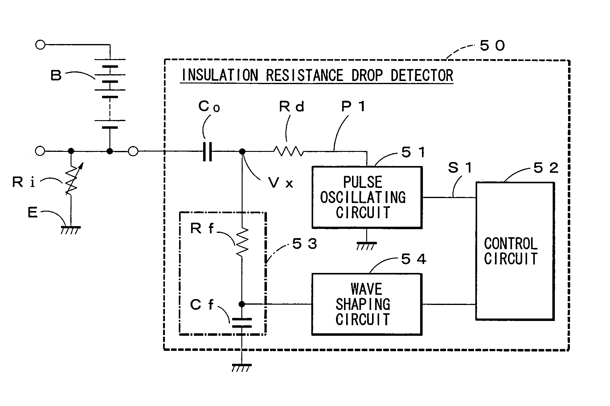
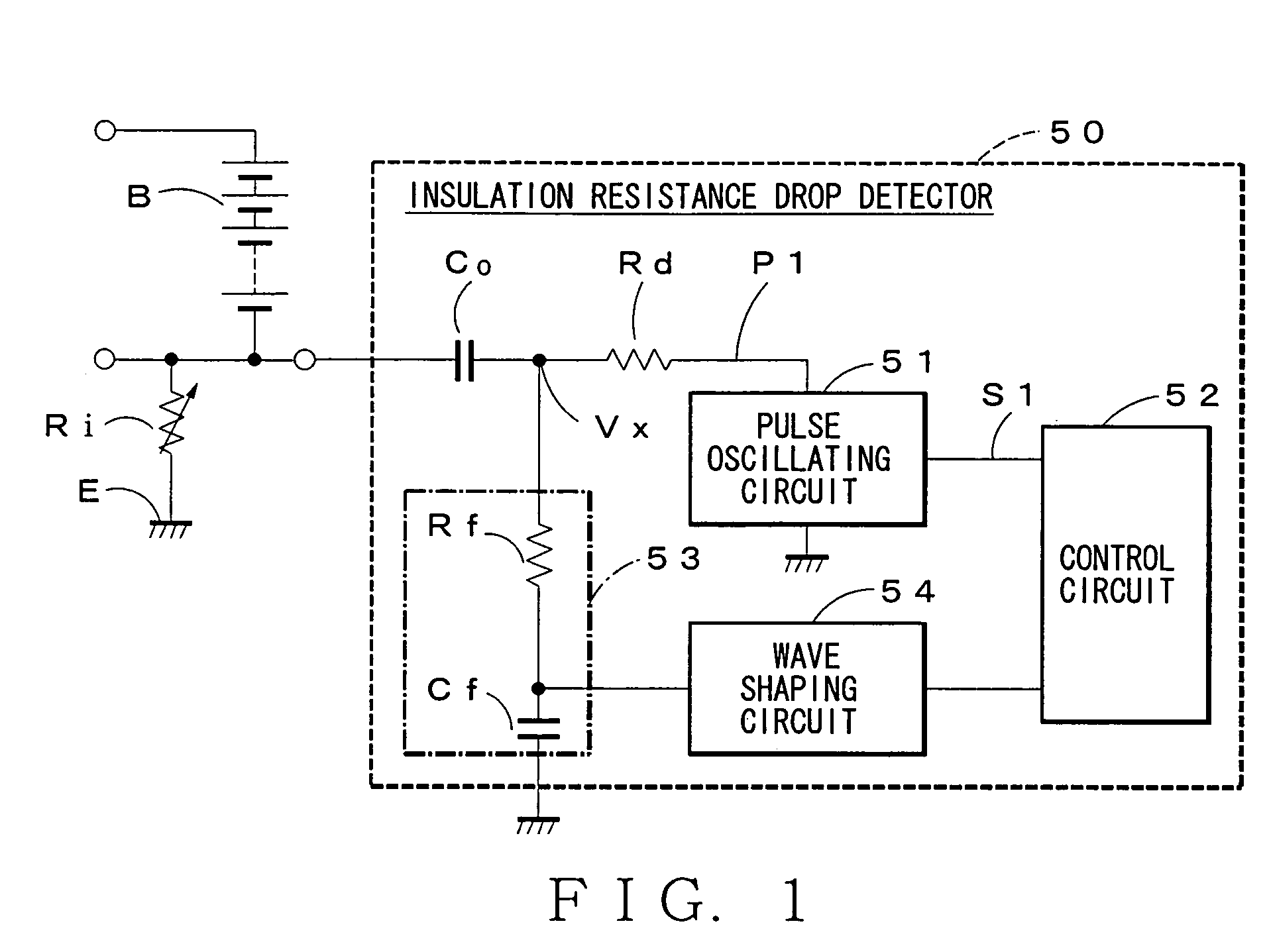
[0035]The method of detecting the state of malfunction of the detector and the insulation resistance drop detector will be explained with reference to drawings, hereafter. FIG. 1 is a circuit diagram showing an embodiment of the insulation resistance drop detector acting the method of detecting the state of malfunction of the detector.

[0036]As shown in FIG. 1, an insulation resistance drop detector 50 has a detecting resistor Rd connected in series with an insulating resistor Ri between a battery supply B as a direct-current power supply and a body of vehicle E, and a coupling capacitor Co disposed between the insulating resistor Ri and the detecting resistor Rd. The detector 50 further includes a pulse oscillating circuit 51 (as the pulse signal generator) for supplying rectangular wave pulse signal P1 with a predetermined peak value to a series circuit structured by the insulating resistor Ri, the coupling capacitor Co and the detecting resistor Rd.

[0037]The pulse oscillating circ...


PUM


Abstract

An insulation resistance drop detector 50 and a method of detecting a state of malfunction of the detector 50 are provided. When open of a coupling capacitor Co or malfunction of a lowpass filter 53 is occurred, a time constant of the low pass filter 53 is decreased and a rising time of an output of the lowpass filter 53 against an output of a pulse signal P1 becomes shorter than that in a state of normal. Thereby, malfunction of the detector 50 can be detected based on the output of the filter 53 corresponding to change of frequency of the pulse signal P1.

Description

BACKGROUND OF THE INVENTION[0001]1. Field of the Invention[0002]This invention relates to a method of detecting a state of malfunction of an insulation resistance detecting circuit (a detector) for detecting a drop of the insulation resistance between a body of vehicle and a direct-current power supply, and the insulation resistance drop detector acting the method of detecting the state of malfunction of the detector.[0003]2. Description of the Related Art[0004]As an aforesaid insulation resistance drop detector, an earth detecting circuit for an electric vehicle described in Patent Document 1 exists. The electric car has a drive circuit system A including a battery unit B for a high voltage (200–300V) direct-current power supply, an inverter 2 as an AC-DC converter for converting direct current supplied through a plus bus line 4 as a positive direct-current supply electric wire and a minus bus line 5 as a negative direct-current supply electric wire from the battery unit B to alter...

Claims


Application Information

Patent Timeline
Patent Type & Authority Patents(United States)
IPC IPC(8): G01R31/00G08B21/00B60L3/00G01R31/02G01R27/02G01R27/18G01R35/00
CPCG01R35/00G01R27/18G01R31/025G01R31/52
Inventor YAMAMOTO, KOUICHIISHIKAWA, SATOSHIUCHIDA, KENJIKATSUTA, TOSHIHIRO
Owner YAZAKI CORP
Why Eureka
Try Eureka