
Load sharing and redundancy scheme

a load sharing and redundancy scheme technology, applied in the field of network technology, can solve the problems of large switchover time, preventing communication between and from each host, and affecting the ability of switches to provide redundancy,

Inactive Publication Date: 2006-02-28
CISCO TECH INC
View PDF51 Cites 91 Cited by
  • Summary
  • Abstract
  • Description
  • Claims
  • Application Information

AI Technical Summary

Benefits of technology

The invention provides a network system with load sharing and redundancy in a network. This is achieved through the use of a master and a slave router operating in the same chassis and sharing interfaces. The master router sends shared state information to the slave router in case of failure. The slave router takes over and operates in standby mode to obtain information from the shared interfaces. The network system also includes a default gateway for both the master and slave routers, as well as forwarding engines for faster forwarding of packets. The master and slave each have a switching processor and a routing processor for layer 2 and layer 3 protocols. The network system also includes a layer 2 database and a layer 3 shortcut table for efficient routing. The master and slave each have a forwarding engine for faster forwarding of packets. The system allows for seamless switchover in case of failure and reduces switchover time.

Problems solved by technology

As described above, a single router failure may prevent communication to and from each host and user connected to the router.
However, when the primary router fails, there is typically a “switchover time” that is required for the backup router to take over the functions of the primary router.
As a result, such attempts to provide redundancy in switches suffer from a large switchover time.

Method used


Image

  • Load sharing and redundancy scheme
  • Load sharing and redundancy scheme
  • Load sharing and redundancy scheme

Examples


Embodiment Construction

[0042]In the following description, numerous specific details are set forth in order to provide a thorough understanding of the present invention. It will be apparent, however, to one skilled in the art, that the present invention may be practiced without some or all of these specific details. In other instances, well known process steps have not been described in detail in order not to unnecessarily obscure the present invention.

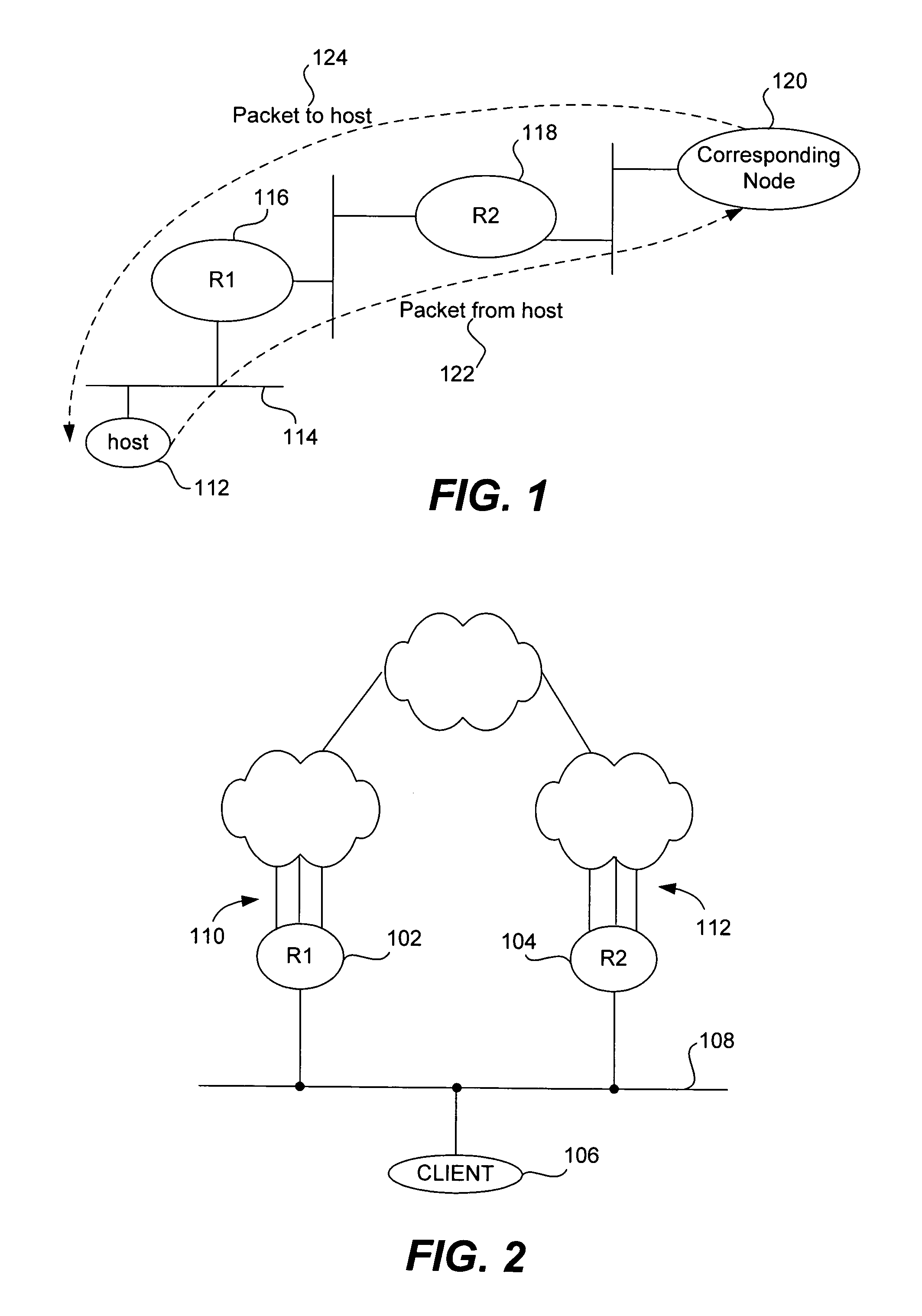
[0043]There are several ways to provide redundancy using multiple routers. For instance, two separate fully operational routers are often used to provide redundancy. FIG. 2 is a diagram illustrating such a system. As shown, a first router R1102 and a second router R2104 are supplied to provide redundancy in a system supporting client 106. The first router R1102 and the second router R2104 share a common interface 108. In addition, the first router R1102 has an associated set of interfaces 110 and the second router R2104 has a separate set of interfaces 112....


PUM


Abstract

Methods and apparatus for providing a device for forwarding packets in a network are disclosed. A first router and a second router having a shared set of interfaces are provided, enabling the first router and the second router to share forwarding data for forwarding packets on the shared set of interfaces.

Description

RELATED APPLICATIONS[0001]This application is a continuation of patent application Ser. No. 09 / 342,859, entitled “Load Sharing and Redundancy Scheme,” naming Kanekar et al. as inventors, filed on Jun. 29, 1999 Now U.S. Pat. No. 6,751,191, which is incorporated herein by reference for all purposes.BACKGROUND OF THE INVENTION[0002]1. Field of the Invention[0003]The present invention relates to networking technology. More particularly, the present invention relates to providing load sharing and redundancy in a network through a master router and a slave router having a shared set of interfaces in a single device.[0004]2. Description of the Related Art[0005]Networks are commonly used by organizations for a variety of purposes. For instance, through the use of networks, resources such as programs and data may be shared by users of the network. In addition, a computer network can serve as a powerful communication medium among widely separated users.[0006]Communication among hosts and user...

Claims


Application Information

Patent Timeline
Patent Type & Authority Patents(United States)
IPC IPC(8): H04J1/16H04L12/46H04L12/56H04L45/02H04L45/58
CPCH04L12/4641H04L45/58H04L45/02
Inventor KANEKAR, BHUSHAN MANGESHRAJENDRAN, SARAVANAKUMARDAVAR, JONATHAN
Owner CISCO TECH INC
Learn More