Device and method for fixing a toner image by solvent vapor while reducing the solvent drag-out

a technology of toner image and solvent vapor, which is applied in the field of devices for fixing toner images, can solve the problems of inability to design too narrow gaps, difficulty in meeting requirements, and inability to eliminate gaps, and achieve the effect of reducing solvent drag-ou

Inactive Publication Date: 2006-02-28
OCE PRINTING SYST
View PDF11 Cites 2 Cited by
  • Summary
  • Abstract
  • Description
  • Claims
  • Application Information

AI Technical Summary

Benefits of technology

[0015]An object of the invention is to provide a device and a method for fixing toner images with the aid of solvent vapor wherein the solvent drag-out is reduced.

Problems solved by technology

Due to the vapor generation, a slight overpressure is generated in the inside of the fixing chamber, this overpressure having the consequence that the solvent vapor exits the fixing chamber, in particular at the relatively large gaps for the entrance and the exit of the carrier web.
These gaps are inevitably present.
In the case when the carrier web is printed on both sides and is linearly guided through the fixing chamber, the gap width cannot be designed too narrow.
This requirement is particularly difficult to meet at the entrance gap and the exit gap for the carrier web.
A contacting or dragging seal, for example by means of a sealing lip or a sealing roller, is not possible at these points.
A contacting, synchronously running sealing roller by which no toner is removed can only be realized at a high economic expense.
A dragging sealing lip might result in a toner removal.
In general, this leads to a considerable solvent consumption which in turn causes high operating expenses.
In addition, the dragged-out solvent can have a negative impact on the ambient air.
In order to be able to keep the admissible work place concentrations for solvents, the fresh air content in the room air has to be very high, which again causes high operating expenses.
With this arrangement, however, the boundary layer at the surface of the carrier web 10 is not reached by the cooling so that the solvent concentration is not reduced thereat, which results in a considerable solvent drag-out in the case of a relatively high transport speed of the carrier web 10.
Further, with this arrangement, a deflection-free, horizontal web guidance as would be required for toner images present on both sides of the carrier web 10 is not possible.
The previous solutions for the problems described are deficient.
The entrance gap and the exit gap cannot be designed arbitrarily narrow, since the passing carrier web, such as paper, presents some forms of unevenness such as waviness over the paper width and can swing or flutter.
In case of a contact with the gap edges, an abrasion or a smearing of the toner on the carrier web can be caused.

Method used


Image

  • Device and method for fixing a toner image by solvent vapor while reducing the solvent drag-out
  • Device and method for fixing a toner image by solvent vapor while reducing the solvent drag-out
  • Device and method for fixing a toner image by solvent vapor while reducing the solvent drag-out

Examples


Embodiment Construction

[0032]For a better understanding, reference is made in the following to the preferred embodiments shown in the drawings, which embodiments are described on the basis of specific terminology. However, it is pointed out that the scope of the invention is not to be restricted thereby since such variations and further modifications to the devices shown and / or to the method as well as such further applications of the invention as shown therein are considered as being common present or future knowledge of the relevant person skilled in the art.

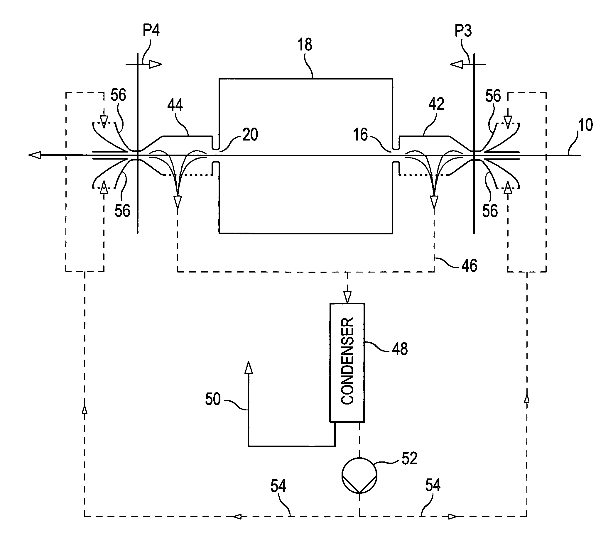
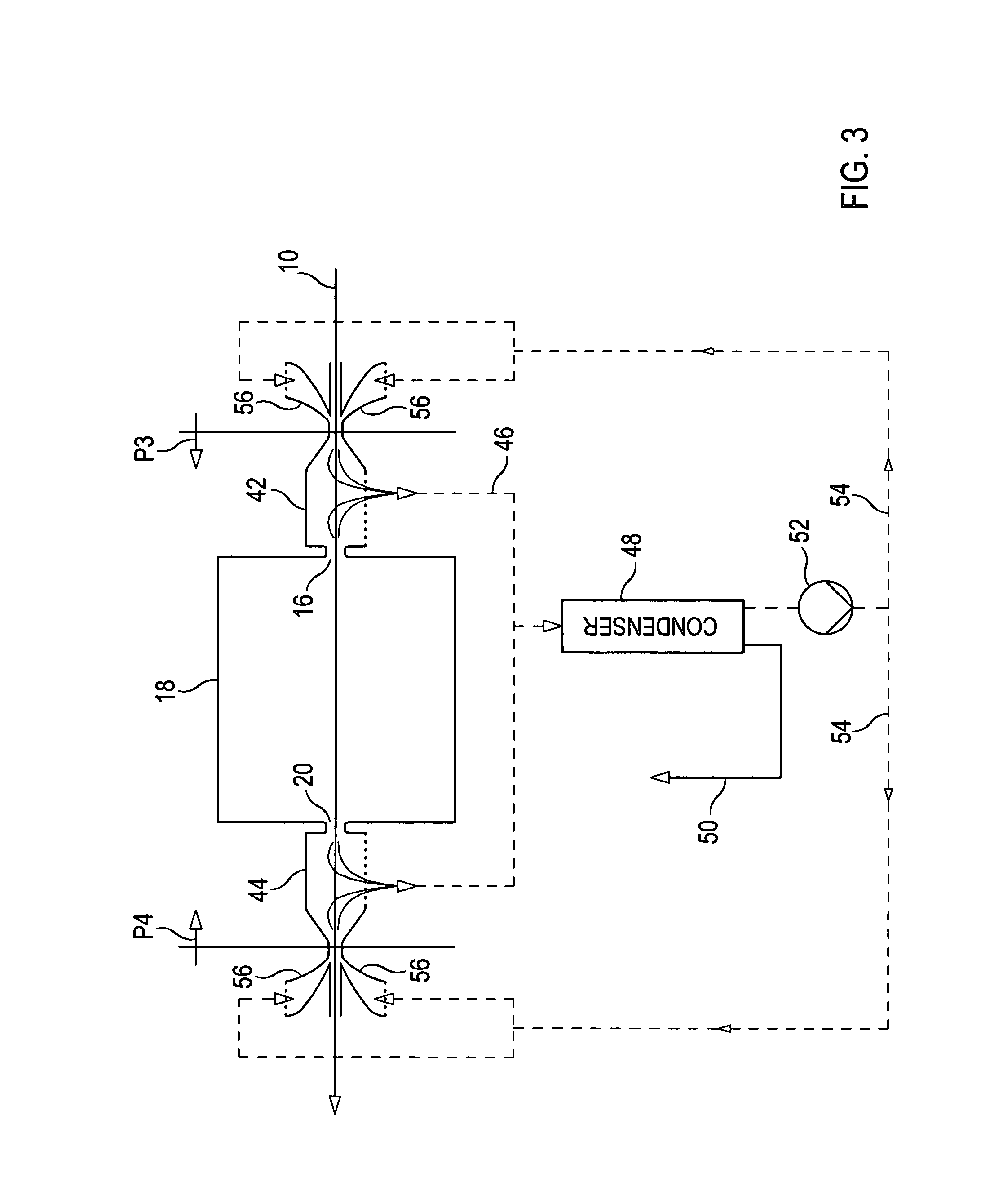
[0033]A rinsing chamber is arranged in front of one of the gaps, i.e. the entrance gap and / or the exit gap, in which rinsing chamber solvent vapor exiting from the gap is mixed with air and the mixture is drawn off. At least part of this drawn-off mixture is supplied to a condenser which condenses and separates solvents. The air exiting the condenser is re-supplied to the rinsing chamber. In this way, a circuit of rinsing air having a considerably r...


PUM


Abstract

In a device and method for fixing toner images on a carrier web, rinsing chambers from which a mixture of solvent vapor and air is drawn off are located before and after a fixing chamber. The mixture is passed through a condenser, the discharge of which is re-supplied to the rinsing chambers.

Description

BACKGROUND OF THE INVENTION[0001]The invention relates to a device for fixing a toner image on a carrier web, comprising a fixing chamber in which toner images present on the carrier web are charged with solvent vapor, the carrier web being supplied to and carried away from the fixing chamber via a respective gap. Further, the invention relates to a method for fixing toner images.[0002]Aside from the fixing of toner images by a contacting heat-pressure treatment and a contactless heat treatment, contactless cold fixing has also gained importance. During this cold fixing, the toner material is softened under the influence of a solvent. The softened toner moistens the surface of the carrier material. When using a carrier material that contains fibers such as, for example, paper or textiles, the softened toner surrounds the fibers and, due to capillary forces, partly penetrates into the spaces between the fibers and into them. After the drying of the carrier material and the evaporatio...

Claims


Application Information

Patent Timeline
Patent Type & Authority Patents(United States)
IPC IPC(8): G03G15/20G03G21/00G03G13/20
CPCG03G15/2096G03G13/20
Inventor KEIDEL, FRANKLANG, ROBERTGOLDMANN, GERDSEGERER, PETERROSENSTOCK, GUNTER
Owner OCE PRINTING SYST
Why Eureka
Try Eureka