Vertical downspouts for gutter system

a gutter system and vertical technology, applied in the field of vertical gutter systems, can solve problems such as not being normally esthetically pleasing, and achieve the effect of convenient replacement and repair, and easy installation and repair

Inactive Publication Date: 2006-03-07
KIM JAY
View PDF12 Cites 23 Cited by
  • Summary
  • Abstract
  • Description
  • Claims
  • Application Information

AI Technical Summary

Benefits of technology

[0018]It is another object of the invention to provide gutters which are easily replaced if damaged.
[0019]

Problems solved by technology

Downspouts are considered functional necessiti

Method used


Image

  • Vertical downspouts for gutter system
  • Vertical downspouts for gutter system
  • Vertical downspouts for gutter system

Examples


Embodiment Construction

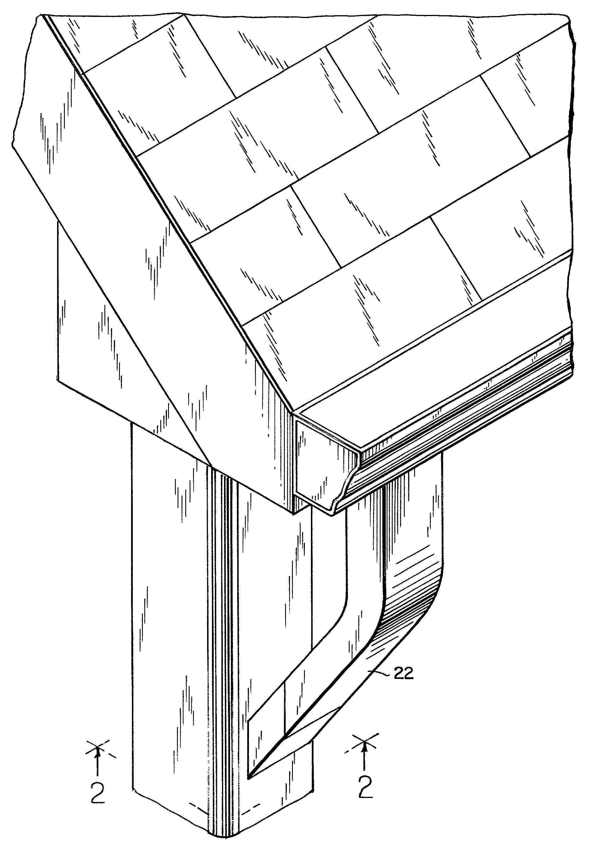
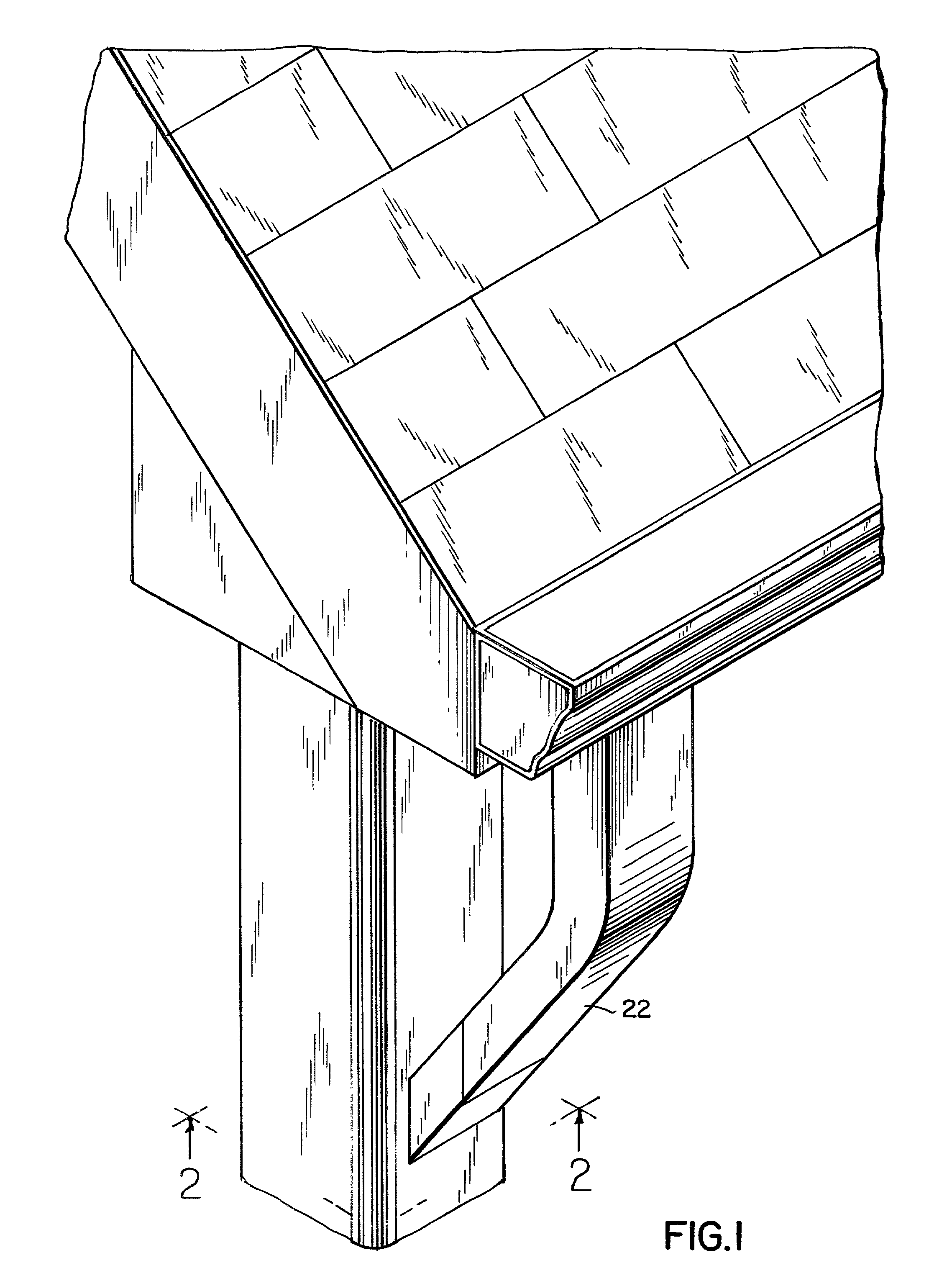
[0035]The vertical downspouts 13 of the invention can be seen in FIG. 1. The vertical downspouts are connected to standard gutters via a standard elbow to receive and transport water collected from the roof of the building.

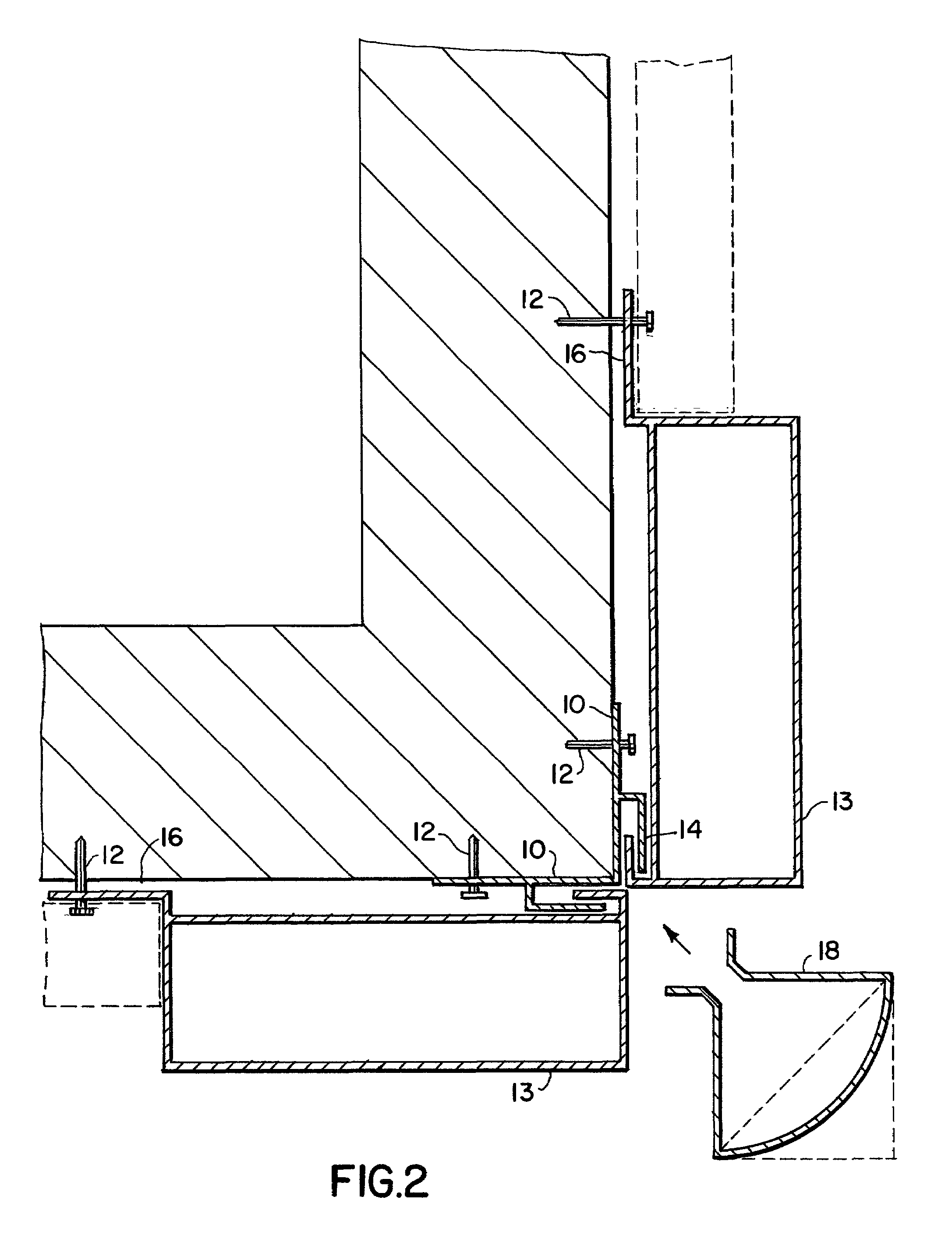
[0036]The attachment of the downspouts to the building is illustrated in FIG. 2. A locking channel 10 has two legs, each leg secured to a side of the building by such means as nails 12. On each leg, an L-shaped locking member 14 opens towards the corner of the building. A downspout 13 having a rectangular cross-section is placed along each wall of the corner. A downspout on each wall proves useful on buildings with hipped roofs having gutters along every edge.

[0037]Each downspout has a rectangular cross section allowing it to fit flush against the wall. A flange 16 extends from the rear wall of the downspout and is secured to the building nails 12. At the edge of the downspout opposite the flange 16, each downspout has an L-shaped locking clip 15. The locking clip...


PUM


Abstract

The downspouts attach to the building by flanges extending from the downspout. The downspouts are attachable to standard gutters and elbows. At the corner of a building, downspouts are attachable to each wall forming the corner and an insert extends between the two downspouts to create a seamless appearance. Siding, brick, or other wall covering for the building extends from the downspouts. Downspouts also can be used in a corner or building, the inside corner of a building having a pair of flanges attachable to the building. Also, the downspouts can be attachable to a post, such as on a porch. The downspout may also contain a right-angle turn. In a right-angle turn, a trap is provided for the easy cleaning of the vertical downspout.

Description

FIELD OF THE INVENTION[0001]The invention pertains to vertical downspouts connected to gutters for removing rain water.BACKGROUND OF THE INVENTION[0002]Gutters with downspouts are used to remove rain water falling upon roofs of houses and buildings. Water is directed toward the edge of the roof and into a gutter. Openings in the bottom of the gutter allow for removal of the water. Vertical downspouts extend from these openings and transport the water to ground level where it is dissipated. Downspouts are considered functional necessities and are not normally esthetically pleasing.[0003]The prior art discloses drainage systems including downspouts intended to blend with the roof and building structure so as to be inconspicuous. One such system is disclosed in U.S. Pat. No. 5,590,492 (Cucchiara et al.). The system uses a trough 20 to collect water from the roof. Collected water is transported under the eaves by a soffit channel 30, which connects with a hollow L-shaped spout post 35. ...

Claims


Application Information

Patent Timeline
IPC IPC(8): E04D13/08E04D13/064
CPCE04D13/0645E04D13/08E04D2013/0893E04D2013/084E04D2013/082
Inventor KIM, JAY
Owner KIM JAY
Why Eureka
Try Eureka