Energy recovery during expansion of compressed gas using power plant low-quality heat sources

a heat source and energy recovery technology, applied in steam engine plants, machines/engines, mechanical equipment, etc., can solve the problems of increasing the cost of gas-stream processing, not applying enhanced energy recovery, etc., and achieve the effect of low quality

Inactive Publication Date: 2006-03-07
THE UNITED STATES AS REPRESENTED BY THE DEPARTMENT OF ENERGY
View PDF23 Cites 92 Cited by
  • Summary
  • Abstract
  • Description
  • Claims
  • Application Information

AI Technical Summary

Problems solved by technology

However, the expansion of the resulting waste gas stream, which is cold and depleted in CO2 content, is not used effectively for energy recovery and the use of low-quality heat sources to heat that gas stream for enhanced energy recovery is not applied.
There is now a growing interest in a method to remove CO2 and other vapors from the flue gas stream at power plants or other industrial combustion facilities (to slow the increase in concentration of atmospheric greenhouse gases and to remove other local pollutants) which will also increase the cost of gas-stream processing.

Method used


Image

  • Energy recovery during expansion of compressed gas using power plant low-quality heat sources
  • Energy recovery during expansion of compressed gas using power plant low-quality heat sources
  • Energy recovery during expansion of compressed gas using power plant low-quality heat sources

Examples


Embodiment Construction

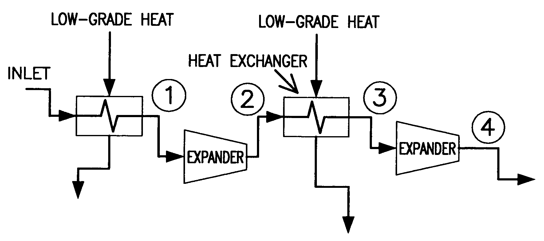
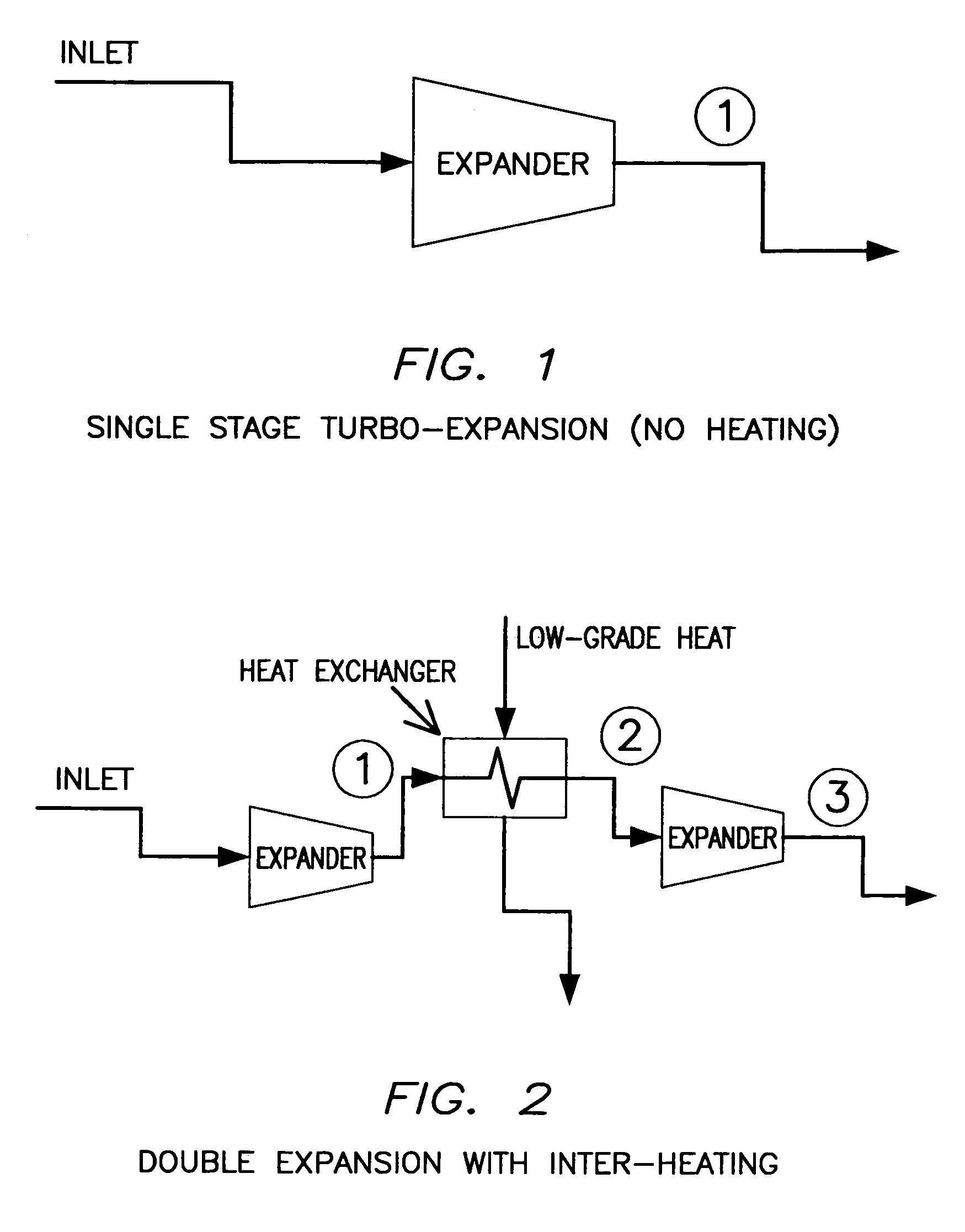
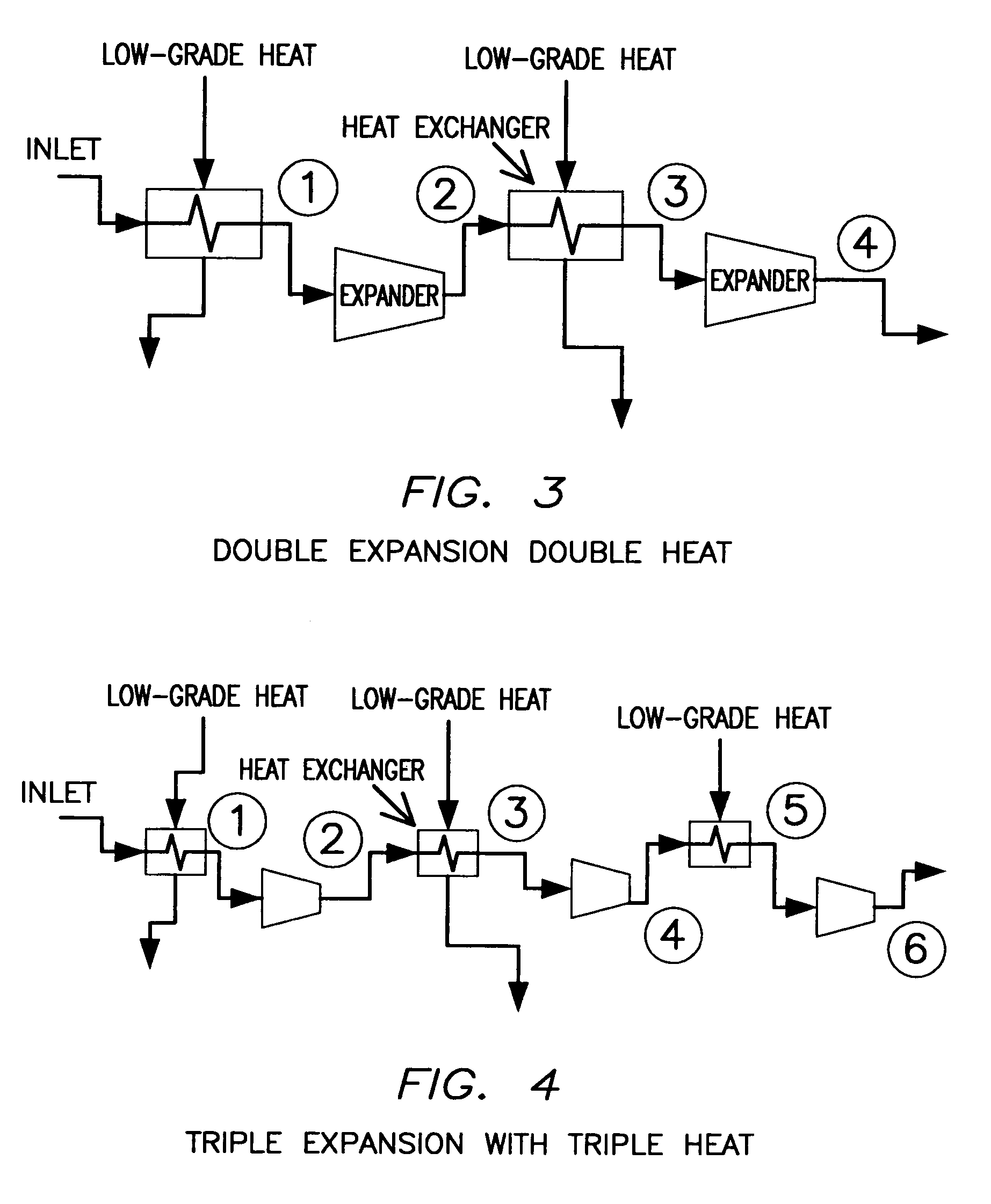
[0014]This invention starts after a gas stream has been compressed and cooled to condense vapor components. In one aspect of the invention a cool high-pressure gas stream is heated using the exit cooling water from a power plant condenser (or other comparable low-quality heat source.) The compressed warm gas is then sent through an expansion engine (such as a turbine) to recover the energy.

[0015]Three applications of this invention are set forth, but it should be readily apparent to those skilled in the arts that there are other applications of the invention.

[0016]In the first application, the invention is used in the setting of a fossil fueled steam power plant using flue gas recirculation, oxygen injection, and flue gas compression and cooling to recover CO2 and pollutants. The cooled, compressed, CO2, SO2, and H2O depleted gas is sent through a heat exchange process with the circulating water (the condenser cooling water for a power plant), and then to the first stage of a 4 stag...


PUM


Abstract

A method of recovering energy from a cool compressed gas, compressed liquid, vapor, or supercritical fluid is disclosed which includes incrementally expanding the compressed gas, compressed liquid, vapor, or supercritical fluid through a plurality of expansion engines and heating the gas, vapor, compressed liquid, or supercritical fluid entering at least one of the expansion engines with a low quality heat source. Expansion engines such as turbines and multiple expansions with heating are disclosed.

Description

CONTRACTUAL ORIGIN OF THE INVENTION[0001]The United States Government has rights in this invention pursuant to employer / employee agreements between the U.S. Department of Energy (DOE) and the inventors.BACKGROUND OF THE INVENTION[0002]This invention relates to a new process for recovering energy from a compressed gas (such as compressed flue gas) which has been cooled and is then reheated using low-quality heat sources such as circulating water in a power plant and then expanded through a turbine (or other expansion engine), to recover the energy in the heated compressed gas stream.[0003]The need for separation of carbon dioxide or other vapor constituents such as sulfur dioxide or water (in this invention the term “vapor” can represent any condensable gas) from a flue gas stream may involve compression of that flue gas stream and cooling of the stream to condense the vapor. Once a portion of the vapor has been removed through condensation, the remaining gas stream can have energy r...

Claims


Application Information

Patent Timeline
Patent Type & Authority Patents(United States)
IPC IPC(8): F01K7/34
CPCF01K7/34F01K7/22
Inventor OCHS, THOMAS L.O'CONNOR, WILLIAM K.
Owner THE UNITED STATES AS REPRESENTED BY THE DEPARTMENT OF ENERGY
Why Eureka
Try Eureka