Refrigeration system utilizing incomplete evaporation of refrigerant in evaporator

a refrigerant and refrigerant technology, applied in the field of refrigeration systems, can solve the problems of difficult for a conventional refrigeration system to reliably restrain an increase in the temperature of the semiconductor device module, and no specific proposal has been made to increase the quantity of heat transfer per unit area, so as to prevent condensation and/or frost, the dew point of the vapor is low, and the effect of preventing condensation

Inactive Publication Date: 2006-03-07
FUJITSU LTD
View PDF64 Cites 68 Cited by
  • Summary
  • Abstract
  • Description
  • Claims
  • Application Information

AI Technical Summary

Benefits of technology

This patent describes a method for maintaining a safe and stable environment inside a semiconductor device by removing excess humidity through a process called dehumidification. A dehumidifier releases moisture into the surrounding area, reducing the likelihood of damage due to cold temperatures and snow accumulation. Additionally, the patent also discusses how a heater can be used to quickly raise the temperature of the internal climate during replacements or maintenance, saving time. Another aspect of the patent focuses on improving efficiency between a cooling element and a semiconductor chip, allowing better thermal management without compromising performance.

Problems solved by technology

This patent discusses two types of refrigeration systems: one used in small computers like servers and another called a dry evaporator which helps keep things cold in larger machines like air conditioners. These systems use different methods to manage their refrigerants, but they both face challenges with keeping up with the increasing amount of heat generated by modern technology. The problem this patent addresses is how to improve the efficiency of these refrigeration systems to better control the temperature of sensitive components without causing damage or malfunction.

Method used


Image

  • Refrigeration system utilizing incomplete evaporation of refrigerant in evaporator
  • Refrigeration system utilizing incomplete evaporation of refrigerant in evaporator
  • Refrigeration system utilizing incomplete evaporation of refrigerant in evaporator

Examples


first embodiment

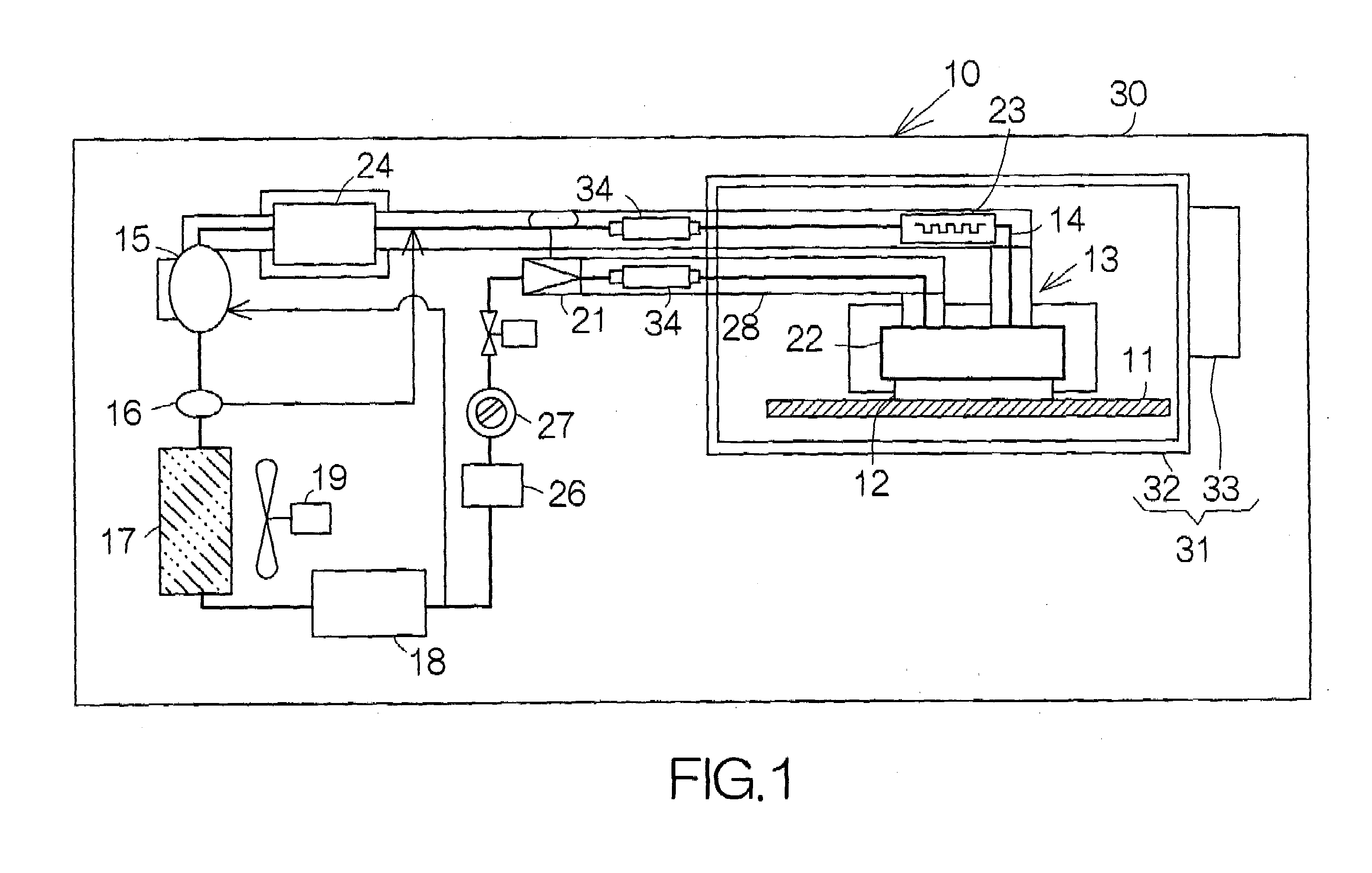
[0131]A refrigeration system 13 of a closed cycle according to the present invention is connected or coupled to the large-sized printed circuit board 11. The refrigeration system 13 is provided with a circulation channel 14 through which a refrigerant of a low boiling point, such as an HFC (R-404A), is allowed to circulate. A compressor 15 is incorporated in the circulation channel 14 for discharging the refrigerant of gas state, namely, a refrigerant gas under a high pressure such as 15 atm, for example. An oil separator 16 is connected to the discharge port of the compressor 15 downstream of the compressor 15. The oil separator 16 is designed to separate the oil included in the refrigerant gas discharged out of the compressor 15. The separated oil is returned to the compressor 15. As conventionally known, the oil serves as a lubricating agent within the compressor 15.

[0132]A condenser 17 is incorporated in the circulation channel 14 downstream of the oil separator 16. The condense...

third embodiment

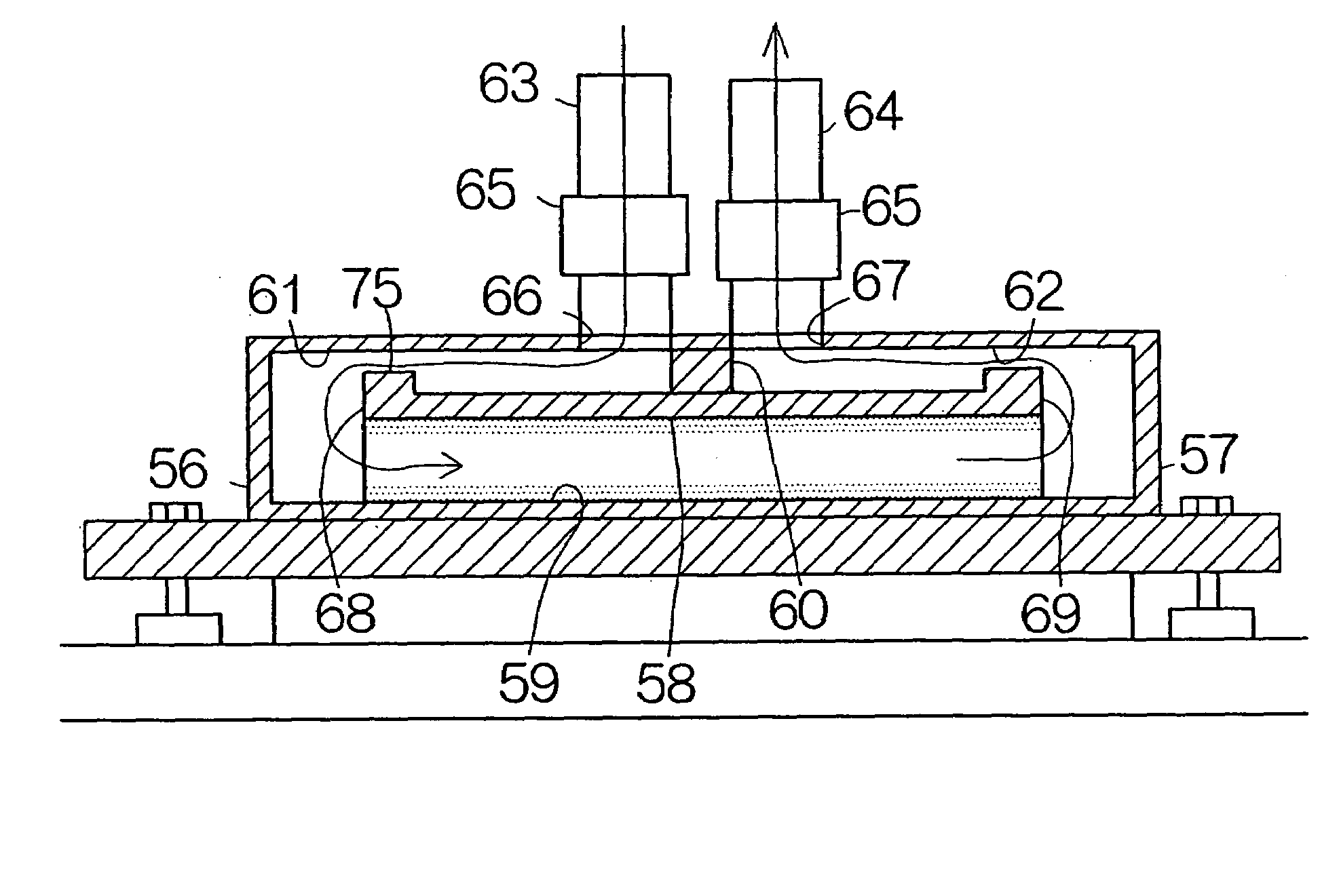
[0206]FIG. 42 schematically illustrates a refrigeration system of a closed cycle according to the present invention. The refrigeration system 230 includes a circulation channel 14 in the same manner as the aforementioned refrigeration system 13. A compressor 15, a condenser 17, a receiver 18, an expansion valve 21, a dry evaporator 22, a subsidiary evaporator 23 and an accumulator 24, in addition to the other components such as an oil separator 16 and a strainer 26, are incorporated in the circulation channel 14 in the same manner as the refrigeration system 13.

[0207]The dry evaporator 22 includes a casing 232 contacting an target heating object such as the semiconductor device module 12 at a vertical heat transfer plate 231, as shown in FIG. 42. A closed space or vaporization chamber 234 is defined between the heat transfer plate 231 and a back plate 233 extending in parallel with the heat transfer plate 231 in the casing 232. The vaporization chamber 234 is allowed to extend in a ...


PUM


Abstract

A refrigeration system allows the refrigerant to circulate through a closed circulation channel. A dry evaporator is incorporated in the circulation channel. The dry evaporator is designed to keep a quality smaller than 1.0 in evaporating the refrigerant. The quantity of heat transfer per unit area, namely, a heat transfer coefficient depends on the quality. The heat transfer coefficient remarkably drops when the quality of the refrigerant exceeds a predetermined threshold level before the quality actually reaches 1.0. The quality of the refrigerant kept below the predetermined threshold level during vaporization of the refrigetant in the dry evaporator allows a reliable establishment of a higher performance of cooling. On the other hand, if a refrigerant completely evaporates in a dry evaporator in a conventional manner, the heat transfer coefficient of the refrigerant remarkably drops after the quality of the refrigerant exceeds the predetermined threshold level. Accordingly, the conventional dry evaporator is forced to absorb heat at a lower heat transfer coefficient, as compared with the present dry evaporator.

Description


Claims


Application Information

Patent Timeline
Owner FUJITSU LTD
Why Eureka
Try Eureka