
Method for comminution of mill feed

a mill feed and comminution technology, applied in the direction of cement production, grain milling, solid separation, etc., can solve the problems of large heat loss flow, inability to convey process air in a closed circuit, and no external energy sources available, so as to reduce the temperature after the mill or the classifier, the effect of reducing the dew point and saving the grinding system

Inactive Publication Date: 2014-12-09
LOESCHE GMBH
View PDF39 Cites 0 Cited by
  • Summary
  • Abstract
  • Description
  • Claims
  • Application Information

AI Technical Summary

Benefits of technology

The invention aims to save energy by using a hot fresh air supply with low moisture content. This technique helps to minimize energy usage and improve efficiency.

Problems solved by technology

For coal grinding plants in the ore industry, the metallurgical industry (blast furnace process) and coal gasification (power plants and chemical industry) there are in the majority of cases no external energy sources available for the drying process in the mill.
For this reason it is not possible to convey the process air in a closed circuit but instead ambient air and / or dry hot gases must be constantly fed to the grinding circuit from externally.
Due to this type of process there is a large heat loss flow, as the gases removed at the flue have a temperature of around 80 to 110° C. and the heat content thereof cannot currently be further used in the grinding system.
Besides this, heat energy is required in order to heat the false air undesirably entering the grinding system from the ambient temperature to the mill outlet temperature, as the penetrated false air must be removed via the flue at this temperature.

Method used


Image

  • Method for comminution of mill feed
  • Method for comminution of mill feed

Examples


Embodiment Construction

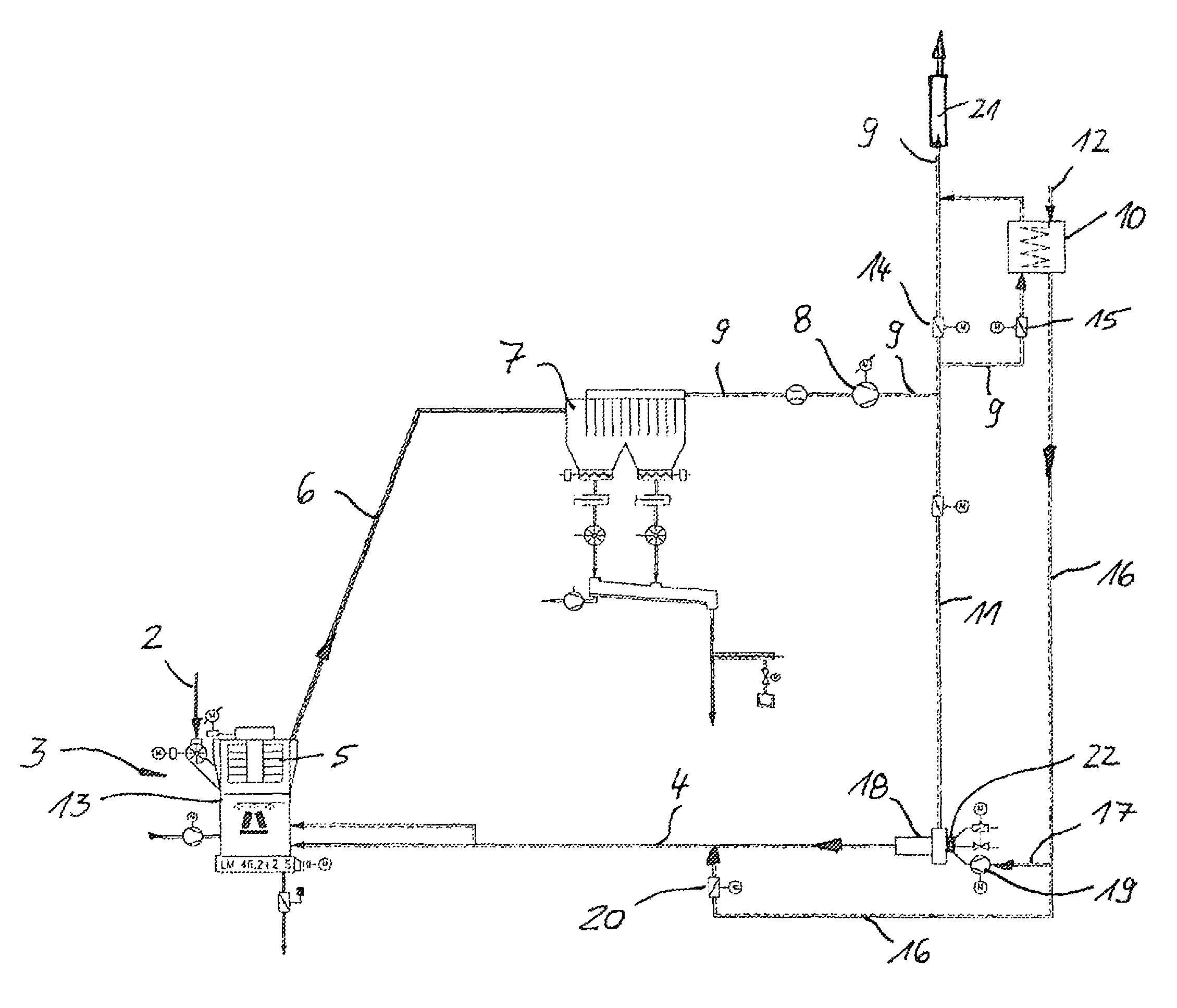
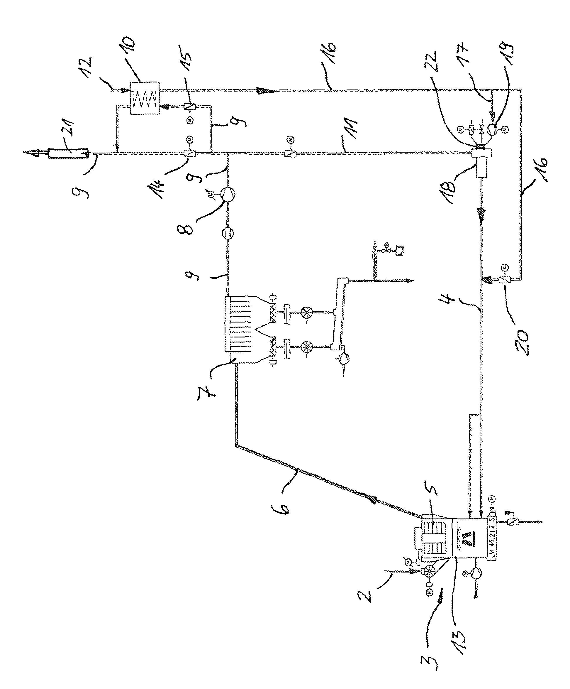
[0029]The invention is explained further below by reference to an example embodiment. The associated drawing shows a flow-sheet of a grinding plant with a mill 3, a classifier 5, a filter 7 and a subsequent mill fan 8 and also with a hot gas generator 18 for generating hot gas 4 or hot air.

[0030]The mill 3 is a vertical air swept mill 13 with an integrated classifier 5. Hot gas 4 or hot air is fed as process gas to the milling chamber of the mill 3 in order to dry moist mill feed 2, for example granulated blast furnace slag or a granulated blast furnace slag / cement mixture or a cement / additive mixture during the comminution. A dust-gas-mixture 6 is conveyed in a connection line, due to the underpressure generated by the mill fan 8, after the mill 3 with the classifier 5 into the filter 7, where the fine material is separated and subsequently the hot exhaust gas 9 is fed via the mill fan 8 to a flue 21 for discharge to the environment. Cement can hereby also be cement clinker.

[0031]A...


PUM


Abstract

The invention relates to a method for comminution of mill feed, in particular for the cement industry, wherein the grinding material is subjected in a mill, in particular an air swept roller mill, to a grinding-drying with supply of a hot gas, is classified and fed as a dust-gas mixture to a filter for dust separation.In order to improve the energy balance and to save heat energy which is generated using a hot gas generator it is provided that fresh gas or fresh air, which is admixed for removal of the moisture of the grinding material in a predefinable portion to the recirculated hot gas or process gas, is preheated before admixing. The preheating of the fresh gas takes place in a heat exchanger through transfer of the heat energy of the process gas to be removed which is then discharged at a lower temperature to the environment. The preheated fresh gas is fed to the grinding circuit and admixed to the recirculation gas at the required points, for example as combustion air or via fresh air dampers, before or in the mill.

Description

BACKGROUND OF THE INVENTION[0001](1) Field of the Invention[0002]The invention relates to a method for comminution of mill feed, in particular for the cement industry as well as the steel industry, ore industry, coal gasification plants for the power plant industry and chemical industry.[0003]The invention is provided in particular for clinker / slag grinding plants in which the grinding material supplied must be subjected to a grinding-drying process. The invention is also suitable for raw powder grinding plants of the cement industry.[0004](2) Description of Related Art[0005]In cement / granulated blast furnace slag grinding plants of the cement industry which are operated in combination with a kiln line system of the clinker burning process, exhaust gases formed in a cement rotary kiln are generally available as a heat source for drying the grinding material.[0006]DE 198 36 323 C2 describes composite grinding plants with air swept roller mills for grinding-drying processes.[0007]Grin...

Claims


Application Information

Patent Timeline
Patent Type & Authority Patents(United States)
IPC IPC(8): B02C11/08B02C23/26B02C15/04B02C23/00
CPCB02C15/04B02C23/26Y02P40/10
Inventor BUCHANENKO, MICHAEL
Owner LOESCHE GMBH
Learn More