Surgical sensor

Inactive Publication Date: 2006-03-07
SURGICAL NAVIGATION TECH
View PDF429 Cites 239 Cited by
  • Summary
  • Abstract
  • Description
  • Claims
  • Application Information

AI Technical Summary

Benefits of technology

[0014]It is an additional object of certain aspects of this invention to provide a reliable localization marker which may be p

Problems solved by technology

Until now, the tracking of anatomical structures has been largely limited to external tracking, either by taping a sensor to a patient's skin, or by affixing an external clamp to the patient, such as a Mayfield clamp, attached externally to a patient's head.
While such related art systems may generally be reliable, their structure is somewhat cumbersome, especially when the movement of multiple anatomical structures needs to be tracked.
In addition, the use of th

Method used


Image

  • Surgical sensor
  • Surgical sensor
  • Surgical sensor

Examples


Embodiment Construction

[0048]The invention will now be described in connection with the Figures wherein like parts are numbered with the same reference numerals for ease of discussion.

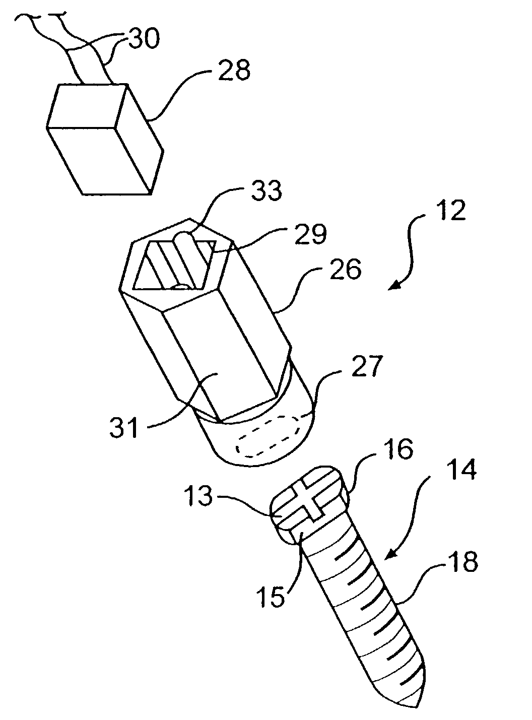
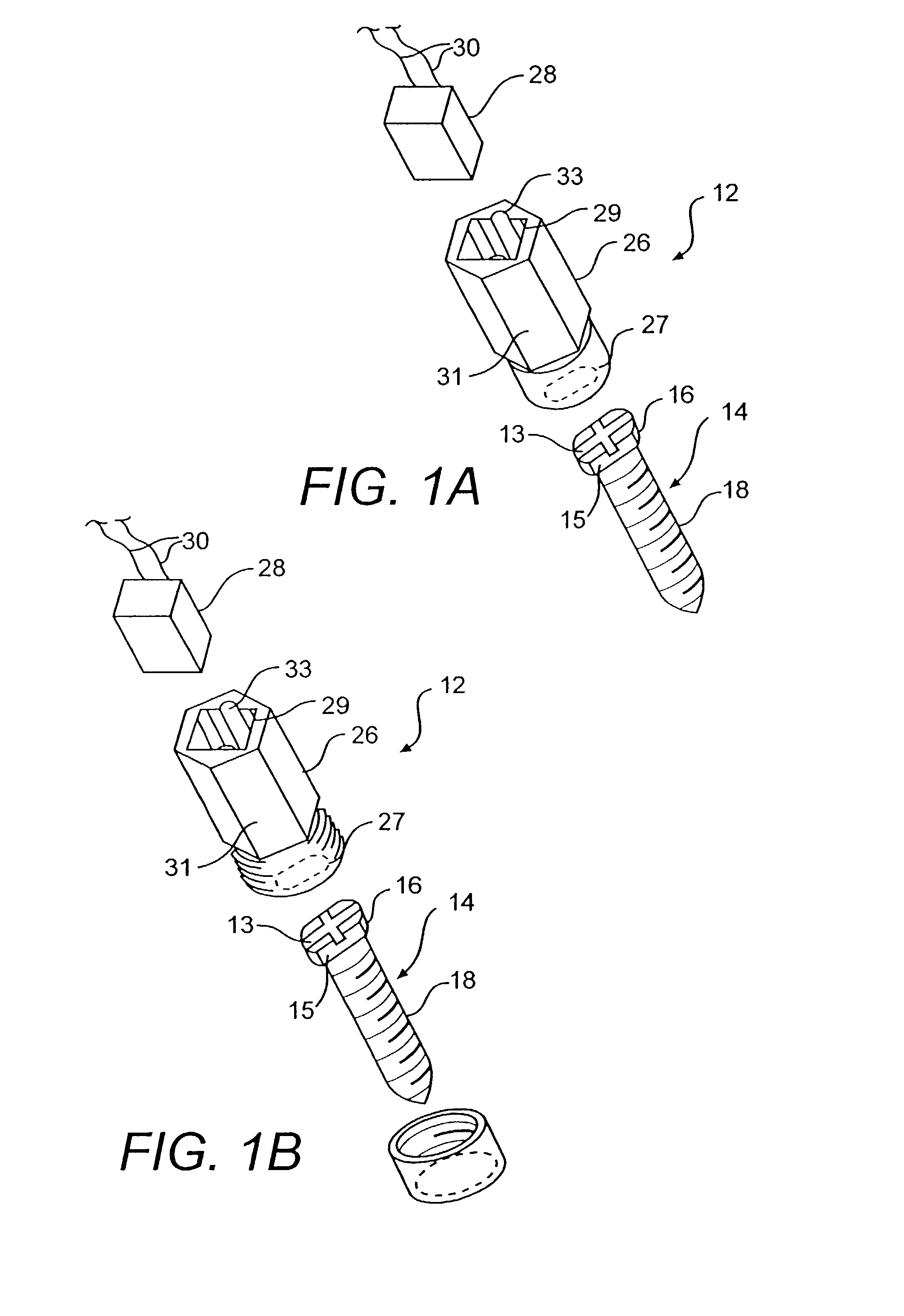
[0049]In accordance with the invention, there is provided an integrated surgical anchor / localization sensor. An example of such an integrated unit is designated by reference number 12 in FIG. 1.

[0050]According to the invention, the anchor is configured to be secured to an anatomical structure. As illustrated in FIG. 1, an anchor in accordance with the invention may, by way of example, include a surgical screw 14. Screw 14 has a head portion 16, and a threaded portion 18. The threaded portion 18 is configured to be secured into boney structure such as portions of long bones, vertebral bodies, the skull, or any other boney anatomical structure. In an preferred embodiment, the anchor may be a 2.2 mm cross-drive screw, 3–7 mm in length. Preferably, the screw has keyed head portions 15 so that a connector may be securely fastened...


PUM


Abstract

An integrated surgical anchor/localization sensor is disclosed. The anchor is adapted to be secured to an anatomical structure and contains a sensor housing. A receiver is located within the sensor housing and is adapted to sense reference signals generated by a surgical guidance system. A transmitter, connected to the receiver, conveys to a processor signals received by the receiver, so that the signals transmitted by the receiver are indicative of a current position of the anchor. Various other structures and methods are also disclosed.

Description

[0001]This application is a continuation of U.S. patent application Ser. No. 09 / 428,721, filed Oct. 28, 1999, now U.S. Pat. No. 6,499,488, the contents of which are incorporated herein by reference in their entirety, and from which priority is claimed.BACKGROUND OF THE INVENTION[0002]1. Field of the Invention[0003]The present invention relates to a surgical sensor which may be integrated with an anatomical anchor. The sensor has particular applicability in surgical procedures where it is desirable to track the relative movement of one or more structures.[0004]2. Description of the Related Art[0005]Many surgical procedures are planned and guided using images obtained from imaging systems such as magnetic resonance imagers (MRIs), computer tomographic imagers (CTs), x-ray imagers, positron emission tomographic (PET) scanners, and photo-emission computer technology (SPECT). These systems permit physicians to obtain detailed preoperative (or intraoperative) views of anatomical structure...

Claims


Application Information

Patent Timeline
IPC IPC(8): A61B19/00
CPCA61B19/5244A61B19/54A61B2017/00477A61B2019/5251A61B2019/5487A61B2019/5416A61B2019/547A61B2019/5483A61B2019/5272A61B2090/3983A61B2034/2072A61B2090/3916A61B34/20A61B2034/2051A61B90/39A61B2090/397A61B2090/3987
Inventor MARTINELLI, MICHAEL A.HUNTER, MARK W.MCCOID, SHERIKESSMAN, PAUL
Owner SURGICAL NAVIGATION TECH
Why Eureka
Try Eureka