Locking device for a telescopic tube assembly

a technology of locking device and telescopic tube, which is applied in the direction of machine supports, mouthpiece/microphone attachments, rod connections, etc., can solve the problems of hindering the performance of locking devices, affecting the safety of lone operators, and unable to hold the weight of illuminating devices, so as to achieve safe completion of relative position adjustment

Active Publication Date: 2006-03-07
HSIEH WU HONG
View PDF4 Cites 23 Cited by
  • Summary
  • Abstract
  • Description
  • Claims
  • Application Information

AI Technical Summary

Benefits of technology

[0011]The primary objective of the present invention is to provide an improved locking device to enable the operator to safely finish the adjustment of the relative position of the inner tube relative to the outer tube with ease.
[0012]Another objective of the present invention is that the locking device of the present invention is able to increase the friction with the inner periphery of the outer tube so as to support the inner tube inside the outer tube.

Problems solved by technology

However, when a distal end of the inner tube (41) is provided with a heavy load, e.g., an illuminating device, it is impossible for the operator to hold the weight of the illuminating device.
That is, it is almost impossible for a lone operator to finish the adjustment of the telescopic tube assembly especially when a weighty object is mounted on the top of the telescopic tube assembly.
Despite the different structure of the three conventional locking devices, there is a common drawback that hinders the performance of the locking devices.

Method used


Image

  • Locking device for a telescopic tube assembly
  • Locking device for a telescopic tube assembly
  • Locking device for a telescopic tube assembly

Examples


Embodiment Construction

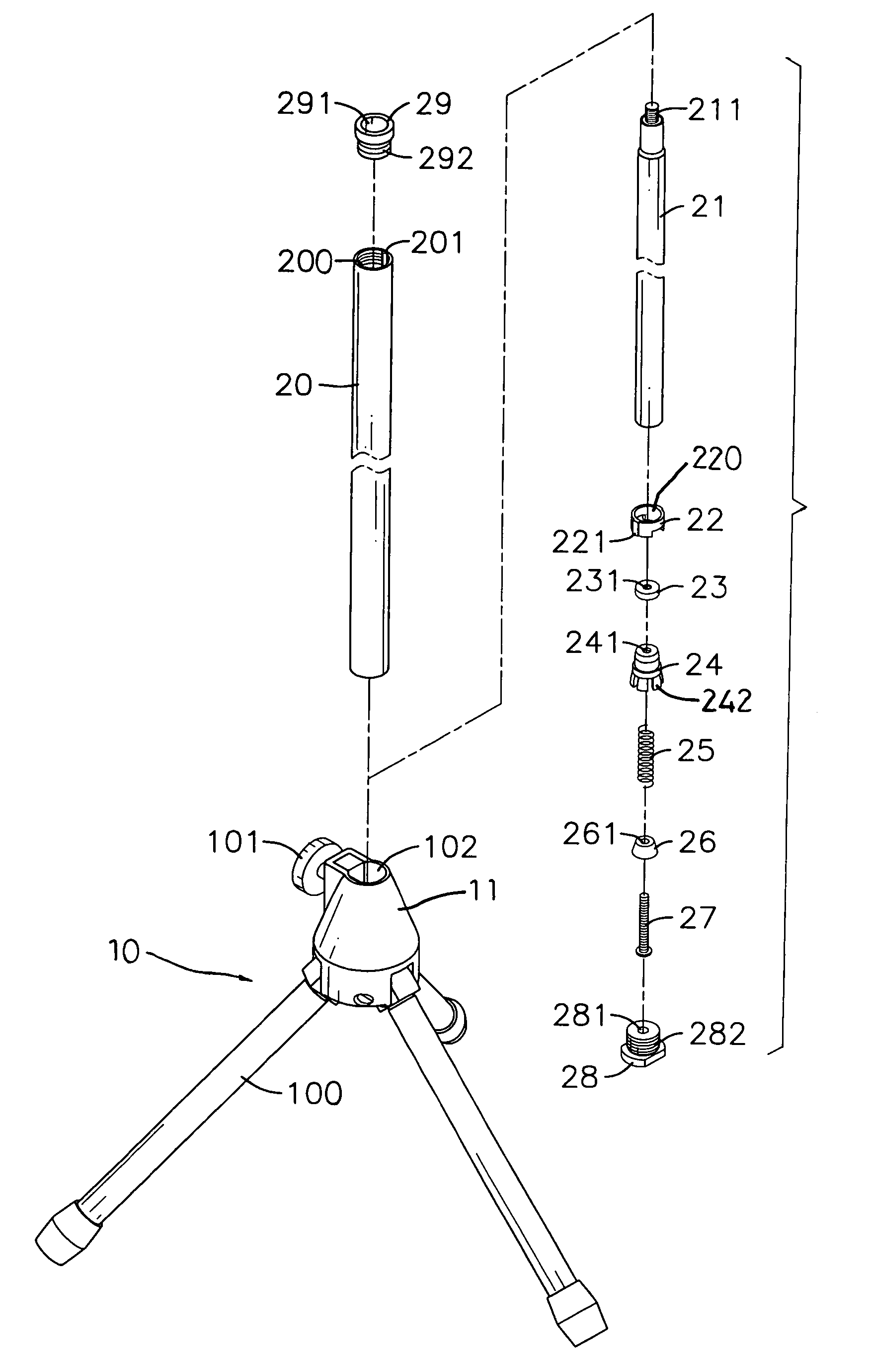
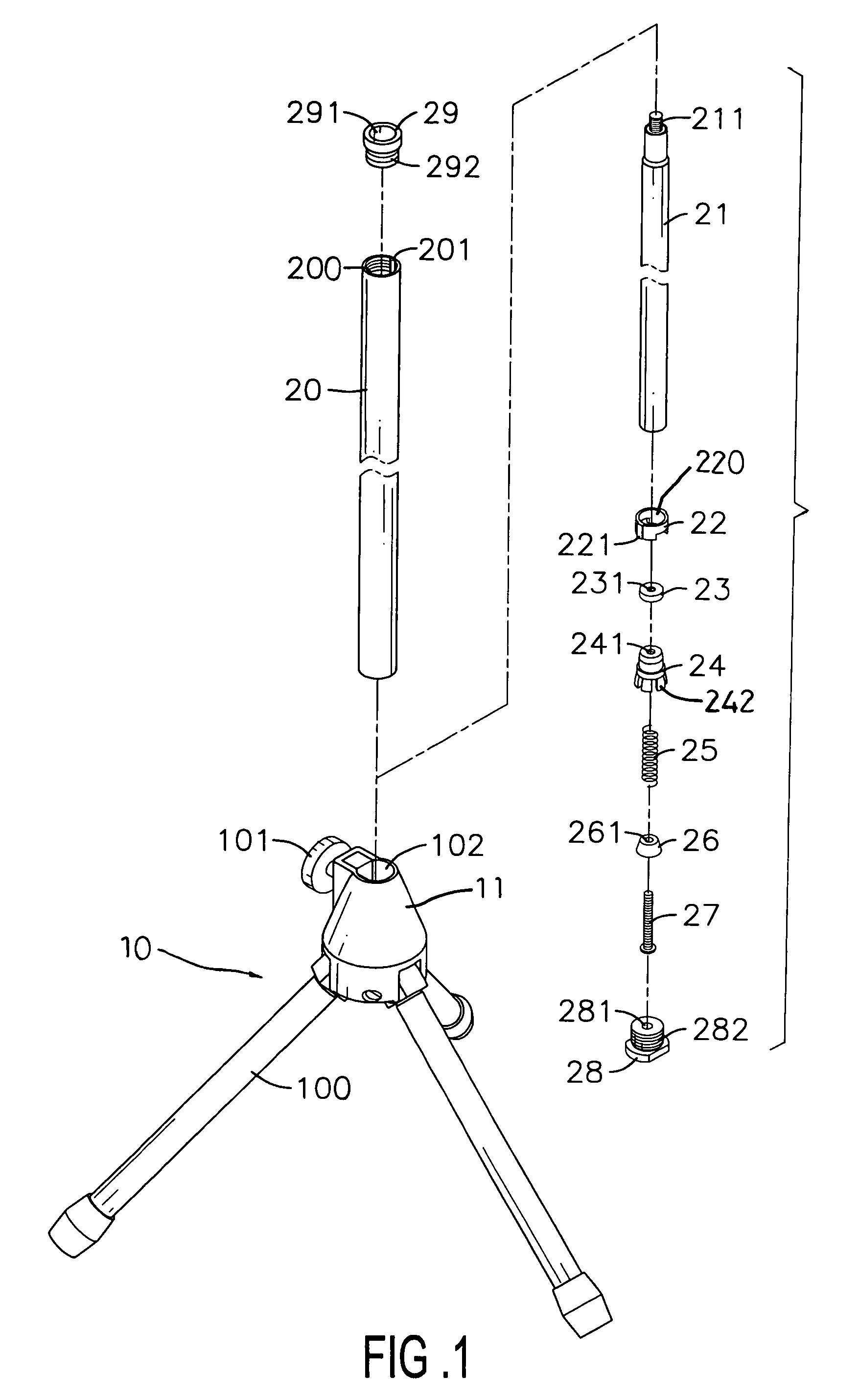
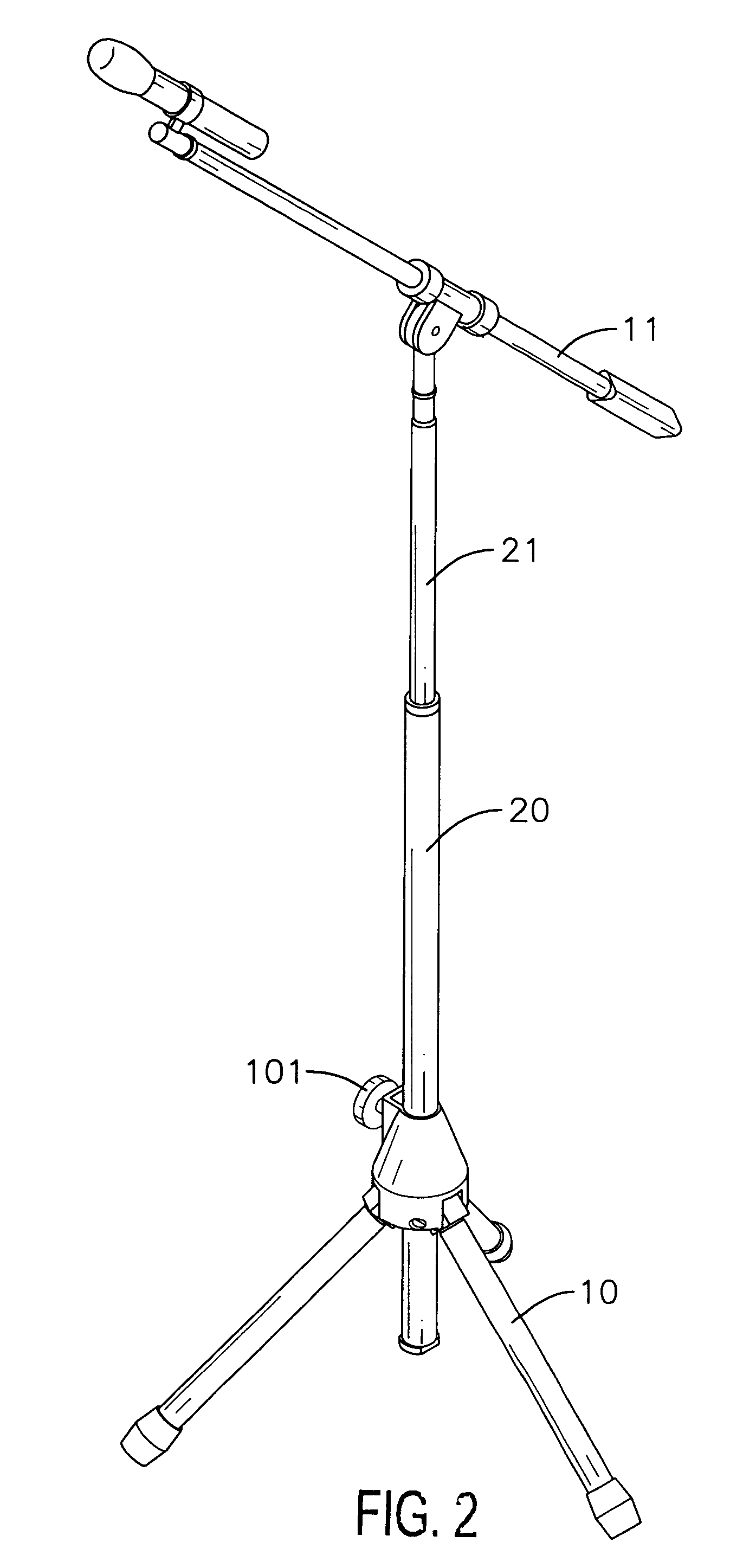
[0020]With reference to FIGS. 1 and 2, a telescopic tube assembly includes an outer tube (20) and an inner tube (21) slidably received in the outer tube (20). The outer tube (20) has inner threading (200) formed on an inner periphery of the outer tube (20) and a guiding groove (201) defined in opposite sides of the inner periphery of the outer tube (20). The inner tube (21) has a threaded rod (211) formed on and extending out of a distal end of the inner tube (21).

[0021]A locking device in accordance with the present invention includes a guiding ring (22), a securing ring (23), a friction element (24), a spring (25), a wedge (26) and a bolt (27). A top cap (29) and a bottom cap (28) are provided to respective openings of the outer tube (20).

[0022]The guiding ring (22) has a first through hole (220) defined through the guiding ring (22) and a guide (221) formed on opposite outer peripheries of the guiding ring (22) to correspond to the guiding grooves (201). The securing ring (23) is...


PUM


Abstract

A locking device for a telescopic tube assembly having an outer tube and an inner tube slidably received in the outer tube includes a securing ring securable inside the inner tube, a friction element adapted to be securely mounted on one distal end of the inner tube and having legs deformably extending out and a wedge adapted to be selectively and movably received inside the outer tube to force the legs to extend toward an inner periphery of the outer tube so as to increase friction between the legs and the outer tube. Thus movement of the inner tube in the outer tube is selectively controlled.

Description

BACKGROUND OF THE INVENTION[0001]1. Field of the Invention[0002]The present invention relates to a locking device, and more particularly to locking device for securing an inner tube in an outer tube of a telescopic tube assembly.[0003]2. Description of Related Art[0004]With reference to FIG. 6, a conventional locking device (30) for a telescopic tube assembly having an outer tube (40) and an inner tube (41) slidably received in the outer tube (40) includes a knob (31) rotatably mounted on a side of the locking device (30).[0005]When the relative position of the inner tube (41) is to be readjusted in relation to the outer tube (40), the operator has to hold the inner tube (41) to prevent the inner tube (41) from slipping too far into the outer tube (40). Then the operator is able to unscrew the knob (51) and change the relative position of the inner tube (41) to the outer tube (40). However, when a distal end of the inner tube (41) is provided with a heavy load, e.g., an illuminating...

Claims


Application Information

Patent Timeline
Patent Type & Authority Patents(United States)
IPC IPC(8): F16M11/00F16B7/14F16M11/28F16M11/38H04R1/08
CPCF16B7/1463F16M11/28H04R1/08F16M11/046F16M11/2021F16M11/242F16M11/048Y10T403/7052F16M2200/027
Inventor HSIEH, WU-HONG
Owner HSIEH WU HONG
Why Eureka
Try Eureka