
Load transfer apparatus

a load transmission device and load technology, applied in the direction of screw, load modified fasteners, fastening means, etc., can solve the problems of difficult to obtain high-reliability sealing, difficult to prevent the leakage of pressure-transmitting medium, difficult to obtain sufficient flexibility, etc., to improve the versatility of the device, reduce the cost and reduce the size and weight of the load transmission device

Inactive Publication Date: 2006-03-07
IMAI ATUSHI
View PDF8 Cites 11 Cited by
  • Summary
  • Abstract
  • Description
  • Claims
  • Application Information

AI Technical Summary

Benefits of technology

[0014]An object of the present invention is to reduce costs in the load transmission device.
[0039]Furthermore, in the present invention, since the load input piston is formed into a disc shape that is made in contact with the inner circumferential face of the housing, and since the pressure-receiving area of the load-transmitting member is set to be smaller than the pressure-receiving area of the load-receiving piston, it is possible to achieve the size and weight reduction of the load transmission device.

Problems solved by technology

In such cases, the above-mentioned seal members fail to withstand such a pressure and a temperature, making it difficult to prevent the leakage of the pressure-transmitting medium.
However, it is difficult to obtain sufficient flexibility since the shearing strength within the limitation of the elasticity of the sealing member is limited and it is also difficult to obtain a highly reliable sealing since the fatigue life is short.
Consequently, in order to deal with such high pressure and high temperature, special expensive sealing members or complex sealing structures need to be used, resulting in cost increase in the load transmission device.
Moreover, the fact that the hydraulic pressure inside the pressure chamber is limited by the characteristics of the sealing member causes the subsequent difficulty in the size and weight reduction of the load transmission device that transmits a greater load.
However, in an attempt to obtain the same output with the pressure-receiving area being reduced, the hydraulic pressure to be supplied to the pressure chamber needs to be increased, with the result that the size and weight reduction of the load transmission device are limited by the performance of the sealing member.
Moreover, there are various kinds of hydraulic oil to be used for load transmission devices of this type, and there are limitations in use conditions such as pressure resistant property, heat resistant property, thermal expansion property and chemical compatibility with the seal member.
Also, when the seal member is damaged, the hydraulic oil might leak from the pressure chamber to cause a fire or the like depending on the installation environments of the device.
Therefore, the installation environments of the load transmission member are limited, resulting in a reduction in its versatility.

Method used


Image

  • Load transfer apparatus
  • Load transfer apparatus
  • Load transfer apparatus

Examples


Embodiment Construction

[0053]Embodiments of the present invention will be described in detail with reference to the drawings.

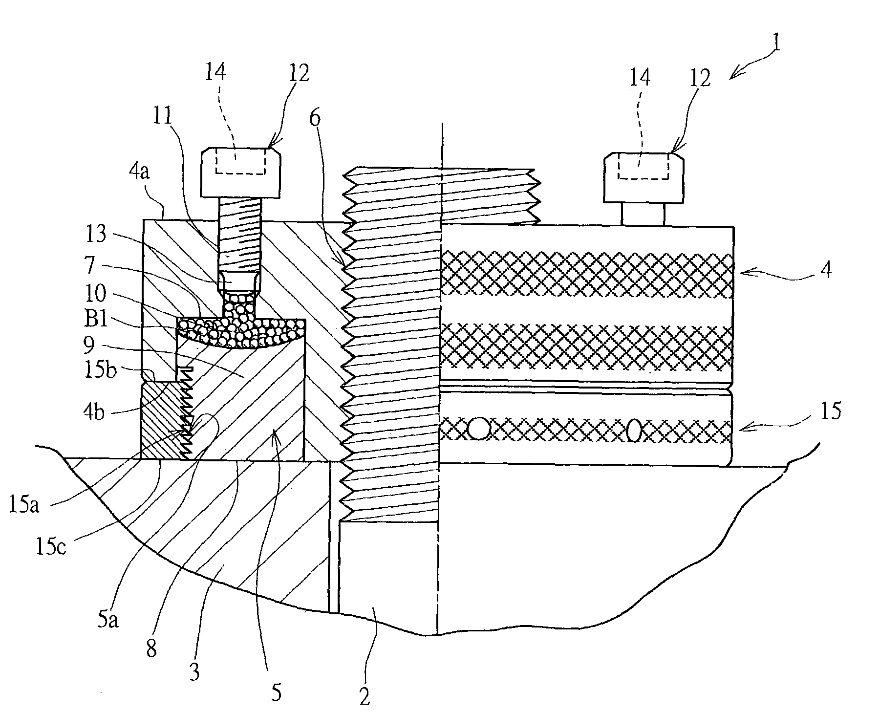
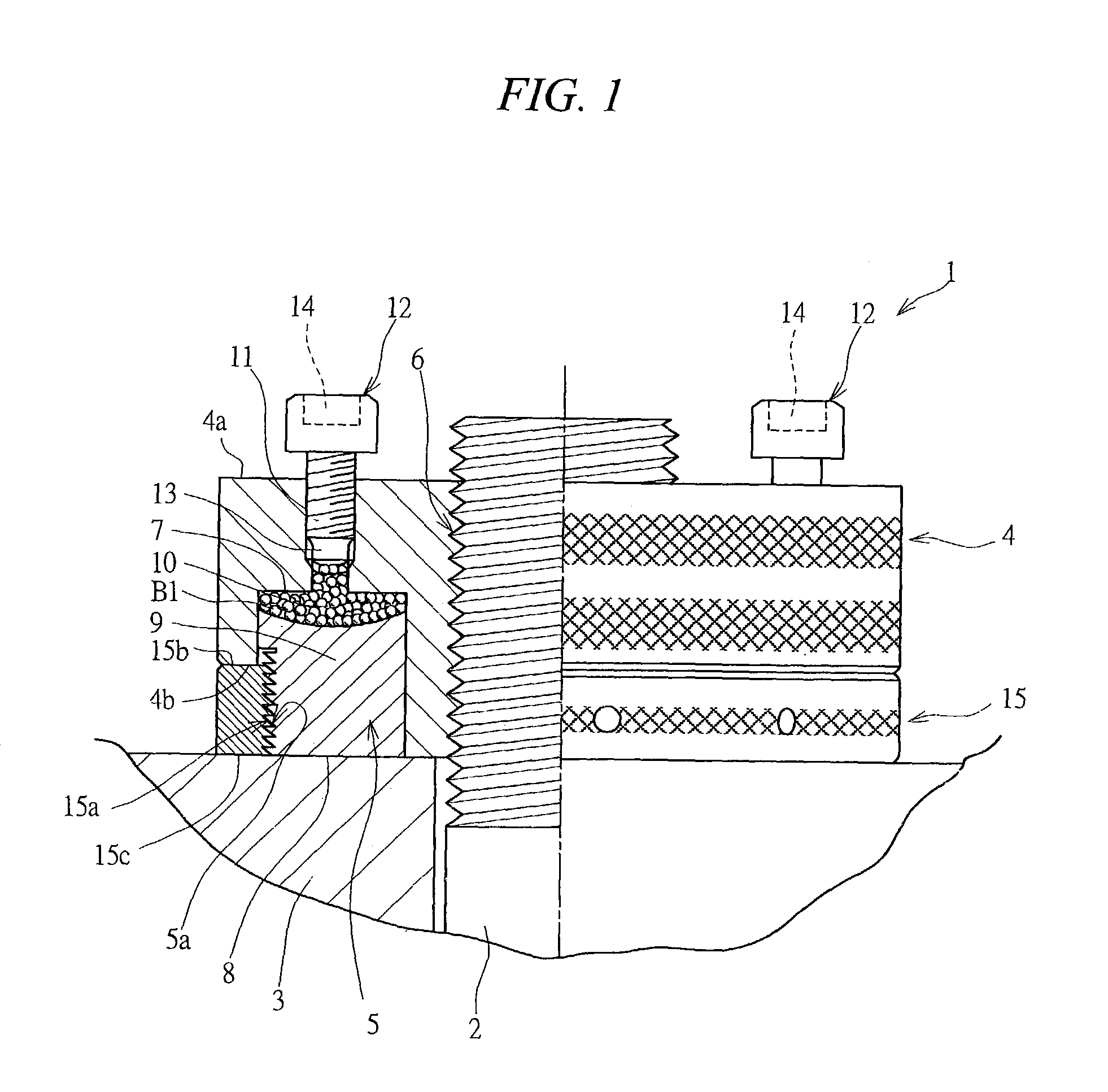
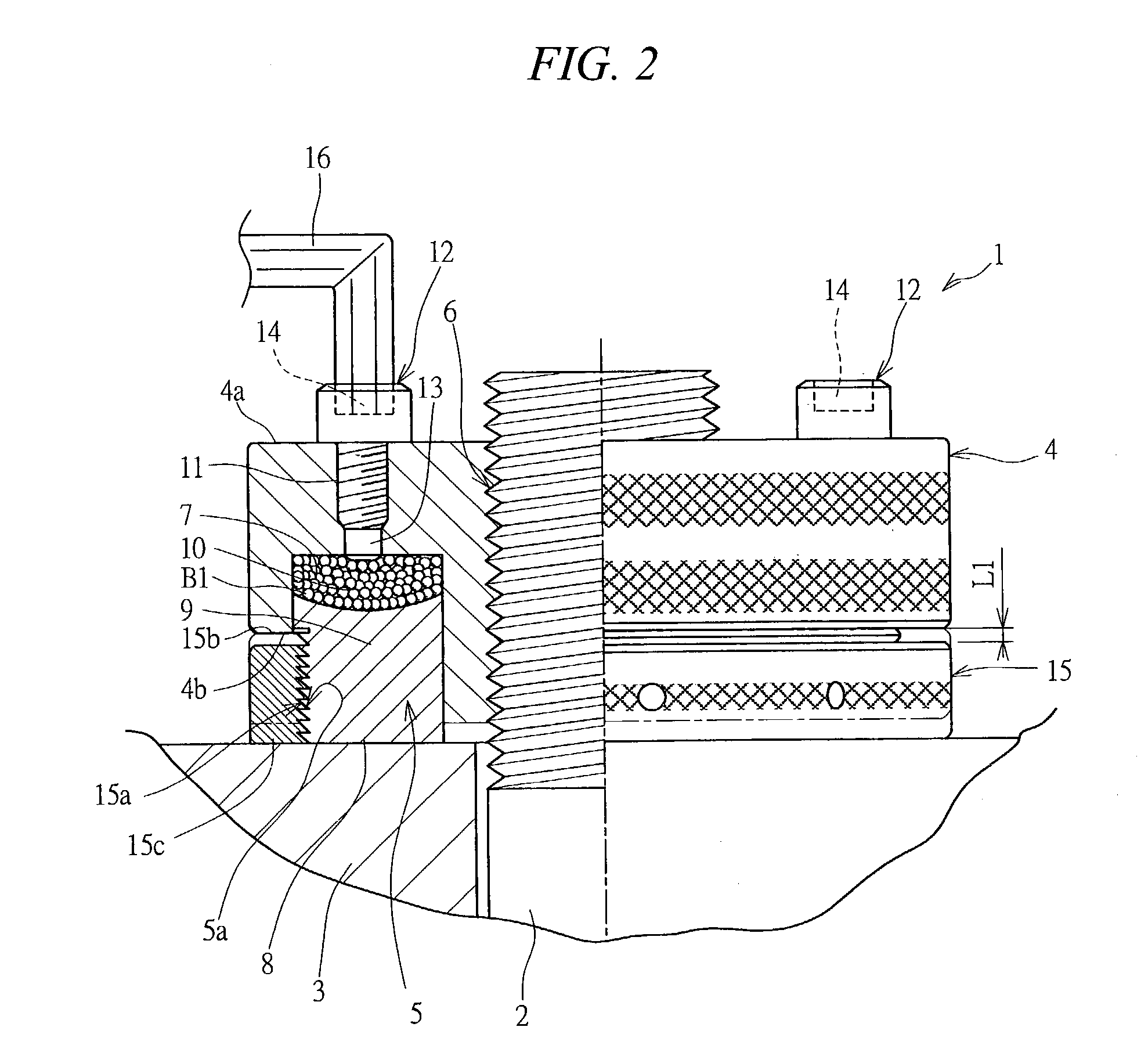
[0054]FIG. 1 is a cross-sectional view that shows an application state (prior to a fastening process) of a nut according to an embodiment of the present invention, and FIG. 2 is a cross-sectional view that shows an application state (after the fastening process) of the nut shown in FIG. 1.

[0055]The nut 1 which serves as a load transmission device is thread-engaged with a bolt 2 so as to fasten a member to be fastened 3, and it preliminarily applies a load on the bolt 2 so as to allow the bolt 2 after the fastening process to have an axial force, thereby preventing the slackness of the fastening. For this reason, the nut 1 is provided with a first load-receiving member 4 and a second load-receiving member 5.

[0056]The first load-receiving member 4 is formed into an approximately ring shape in its outer shape and provided with a screw hole 6 that is screw-engaged with a bolt 2 that is ...


PUM


Abstract

A first load-receiving member having a cylinder and a screw hole through which a bolt is thread-engaged and a second load-receiving member having a piston and a fastening face that is made in contact with a member to be fastened are attached to a nut, and a number of balls made of steel the surface of which is lubricated by grease are loaded into a pressure chamber that is formed as a compartment by the cylinder and the piston. Since these balls exert fluidity in the pressure chamber, a load applied to the balls is transmitted to the cylinder and the piston through the balls by screwing the input bolt. Thus, the first load-receiving member is moved in the axis direction with respect to the second load-receiving member, thereby applying a tensile force to the bolt.

Description

TECHNICAL FIELD OF THE INVENTION[0001]The present invention relates to a load transmission device which transmits a load inputted from a load-applying means to a load-receiving member through a pressure-transmitting medium.BACKGROUND OF THE INVENTION[0002]A load transmission device is provided with a first load-receiving member and a second load-receiving member that is assembled so as to be relatively movable with respect to the first load-receiving member, and a pressure chamber is formed as a compartment between these load-receiving members. The pressure chamber is filled with a pressure-transmitting medium, and a pressure, that is, a load applied by the load-applying means is transmitted to the first and second load-receiving members through the pressure-transmitting medium. With respect to the pressure-transmitting medium for use in such a load transmission device, a fluid such as hydraulic oil and nitrogen gas is generally used.[0003]With respect to devices using hydraulic oil...

Claims


Application Information

Patent Timeline
Patent Type & Authority Patents(United States)
IPC IPC(8): F16B31/00F16B2/16F16B31/04
CPCF16B31/04F16B2/16
Inventor IMAI, AKIRAIMAIGODA, TATSUO
Owner IMAI ATUSHI
Learn More