

Rotor for cooling pumps, in particular for marine engines and relevant manufacturing process
- Summary
- Abstract
- Description
- Claims
- Application Information
AI Technical Summary
Benefits of technology
Problems solved by technology
Method used
Image

Examples
Embodiment Construction
[0014]This invention will be now described in detail, by way of a not limitative example, with reference to the enclosed figures; in which:
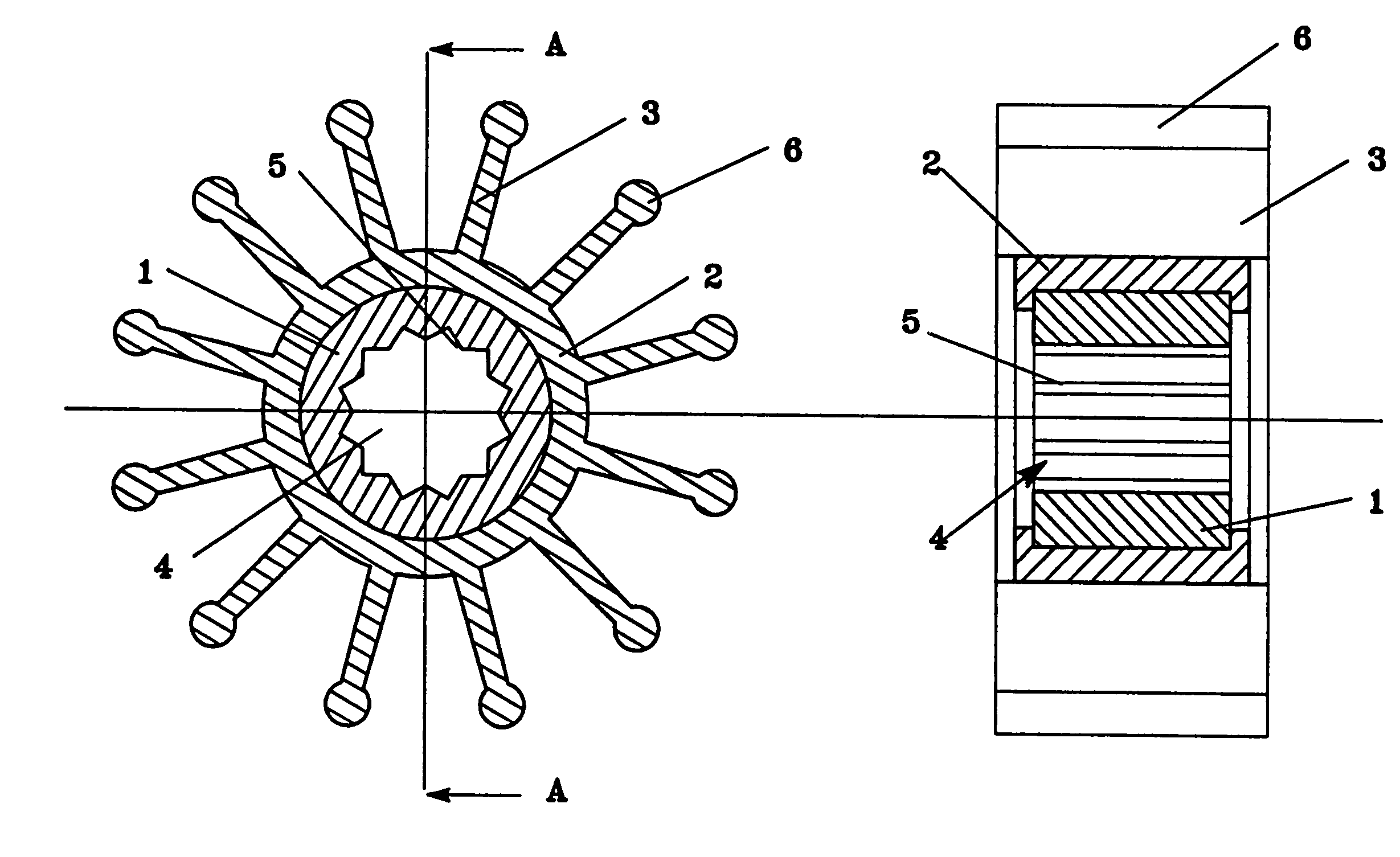
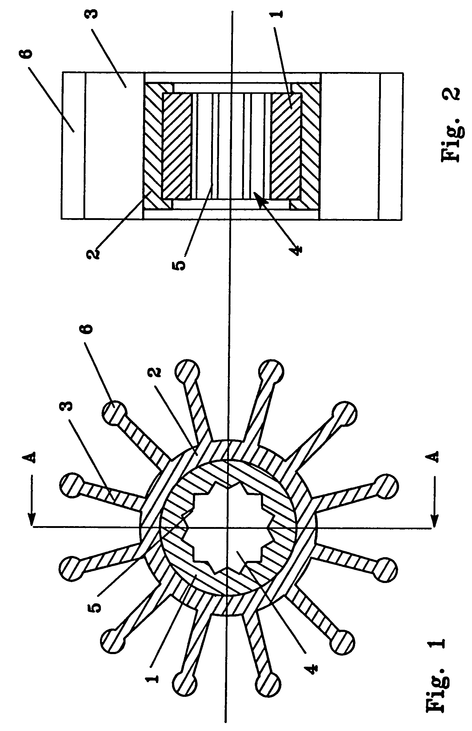
[0015]FIG. 1 shows the section of a rotor according to the invention along a plane perpendicular to the axis of the rotor;
[0016]FIG. 2 is the section along the line A—A of FIG. 1.
[0017]With reference to the enclosed figures, the rotor according to the invention essentially comprises a core 1 onto which a body 2 is fitted in, provided with a plurality of tabs 3 of flexible material.
[0018]The core 1, which is addressed to be assembled on a shaft connected with engine means, shows a through hole 4 provided internally with a toothing 5 or another known system able to constrain under rotation the core and the shaft onto which the core is assembled.
[0019]The body 2 is preferably injected directly on the core and the tabs 3 show preferably the ends 6 which are addressed to flow in contact with the pump chamber walls, swollen for example with a substanti...
PUM
| Property | Measurement | Unit |
|---|---|---|
| Size | aaaaa | aaaaa |
| Flexibility | aaaaa | aaaaa |
| Hardness | aaaaa | aaaaa |
Abstract
Description
Claims
Application Information