Molding apparatus with removable mold cores

a mold core and mold technology, applied in the field of mold core molding apparatus, can solve the problems of defective products during the production of lenses, adversely affecting the production efficiency, and time-consuming, and achieve the effect of quick replacement and enhanced production efficiency

a mold core and mold technology, applied in the field of mold core molding apparatus, can solve the problems of defective products during the production of lenses, adversely affecting the production efficiency, and time-consuming, and achieve the effect of quick replacement and enhanced production efficiency

US7008212B2Inactive Publication Date: 2006-03-07ASIA OPTICAL INT LTD

Image

  • Molding apparatus with removable mold cores
  • Molding apparatus with removable mold cores
  • Molding apparatus with removable mold cores

Examples


Embodiment Construction

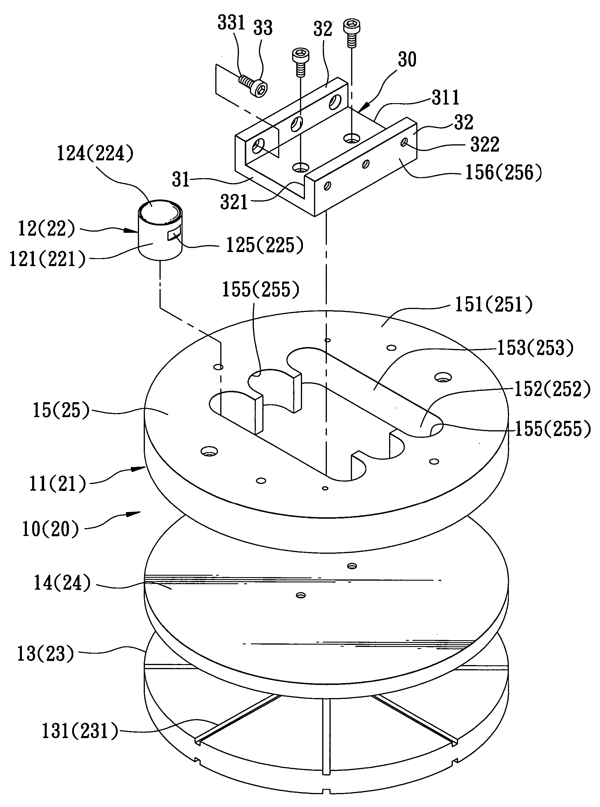
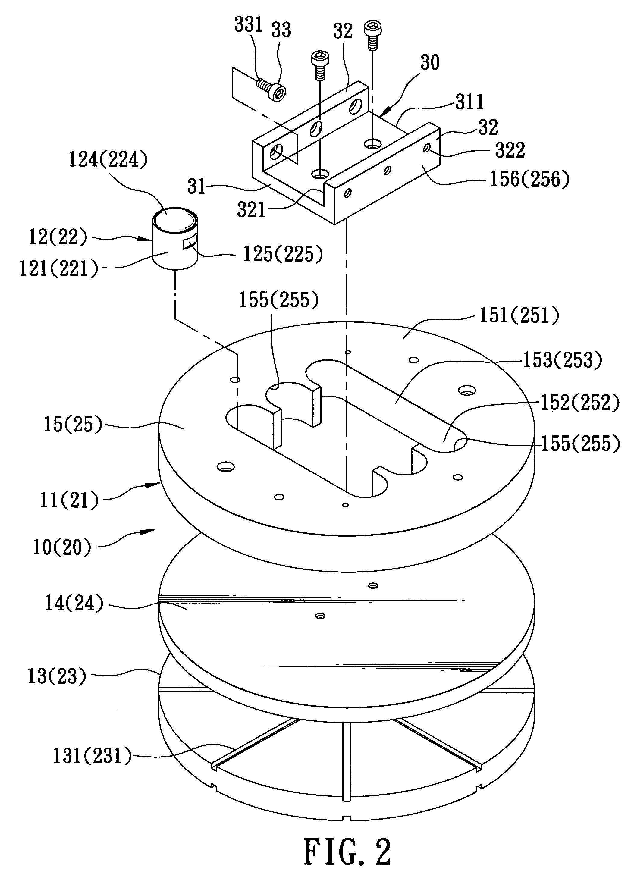
[0019]Referring to FIGS. 2 to 5, the preferred embodiment of a molding apparatus for lenses according to the present invention is adapted to be mounted on a support assembly 100. The support assembly 100, as shown in FIG. 4, includes a first support seat 110 and a second support seat 120 opposite to the first support seat 110. The molding apparatus of the present invention comprises a first molding unit 10 mounted on the first support seat 110, and a second molding unit 20 mounted on the second support seat 120 and facing the first molding unit 10.

[0020]Each of the first and second molding units 10, 20 has a mold core holder 11, 21, a plurality of mold cores 12, 22, and a clamp unit 30.

[0021]The mold core holder 11, 21 includes a base plate 13, 23, a cooling plate 14, 24 superimposed upon the base plate 13, 23, and a mold plate 15, 25 superimposed upon the cooling plate 14, 24. The base plate 13, 23, the cooling plate 14, 24, and the mold plate 15, 25 are secured together to form a ...


PUM

PropertyMeasurementUnit
shapeaaaaaaaaaa
outer diameter toleranceaaaaaaaaaa
inner diameter toleranceaaaaaaaaaa

Abstract

A molding apparatus for lenses includes first and second molding units, each of which has a mold core holder, a plurality of mold cores disposed in the mold core holder, and a clamp unit provided within the mold core holder. The mold core holder has an abutment surface, and a plurality of cavities extending inwardly from the abutment surface and receiving respectively the mold cores. The cavities include cavity walls, respectively. The clamp unit includes a plurality of clamp elements attached to the clamp unit to clamp respectively the mold cores against the cavity walls. Individual removal of the mold cores of the molding units for replacement is permitted by operating the clamp elements.

Description

CROSS-REFERENCE TO RELATED APPLICATION[0001]This application claims priority of Taiwanese Application No. 093102812, filed on Feb. 6, 2004.BACKGROUND OF THE INVENTION[0002]1. Field of the Invention[0003]The invention relates to a molding apparatus for lenses, more particularly to a molding apparatus that has individually removable mold cores.[0004]2. Description of the Related Art[0005]Referring to FIG. 1, a currently available molding apparatus for lenses includes a lower mold unit 1 and an upper mold unit 2 facing the lower mold unit 1. The lower mold unit 1 has a lower mold core holder 101, a plurality of lower mold cores 102 disposed within the lower mold core holder 101, and a lower fixed seat 103 to be fixed to a bottom portion of the lower mold core holder 101 so as to retain the lower mold cores 102 in the lower mold core holder 101. The lower mold core holder 101 is formed with a plurality of lower mold core holes 104, each of which has a narrow upper portion and a wider lo...

Claims


Application Information

Patent Timeline
07 Mar 2006
Publication
US7008212B2
IPC
B29C33/30; B29D11/00
CPC
B29C45/2675; B29D11/00432; Y10S425/808; B29L2011/0016
Inventors
YANG, CHUAN-HUI