Tooth brusher

a tooth brush and tooth brushing technology, applied in the field of tooth brushing devices, can solve the problems of difficult to remove teeth from such portions, consuming too much time for him, and being tired on his arm, and it is not easy to continue the work any longer

Inactive Publication Date: 2006-03-07
RICOH ELEMEX CORP
View PDF8 Cites 36 Cited by
  • Summary
  • Abstract
  • Description
  • Claims
  • Application Information

AI Technical Summary

Benefits of technology

[0010]In the invention described in claim 2, water blown out from the blow-out port is directed to the end of the brush in addition to the constitution of the invention of claim 1. Thus, water blown out from the blow-out port is directed to the end of the brush making it possible to concentrate the water flow blown out from the nozzle onto the bristle tips of the brush and, hence, to efficiently wash, out of the pocket, the sordes and foul matter peeled off the tooth surface by brushing.

Problems solved by technology

It has been widely known that sordes on teeth are difficultly removed from such portions as gum grooves among the teeth and pockets deep in the gum grooves.
With this method, however, a persevering manual work must be conducted for every portion requiring a brushing time of not less than one hour, and a person finds himself tired on his arm consuming too much time and finds it not easy to continue the work any longer.
Therefore, it becomes highly probable that the bristle tips are stuck to the inflamed gum causing a severe pain not only when the patient brushes his teeth by himself but also when the patient has his teeth brushed by an expert such as a dentist.

Method used


Image

  • Tooth brusher
  • Tooth brusher
  • Tooth brusher

Examples


first embodiment

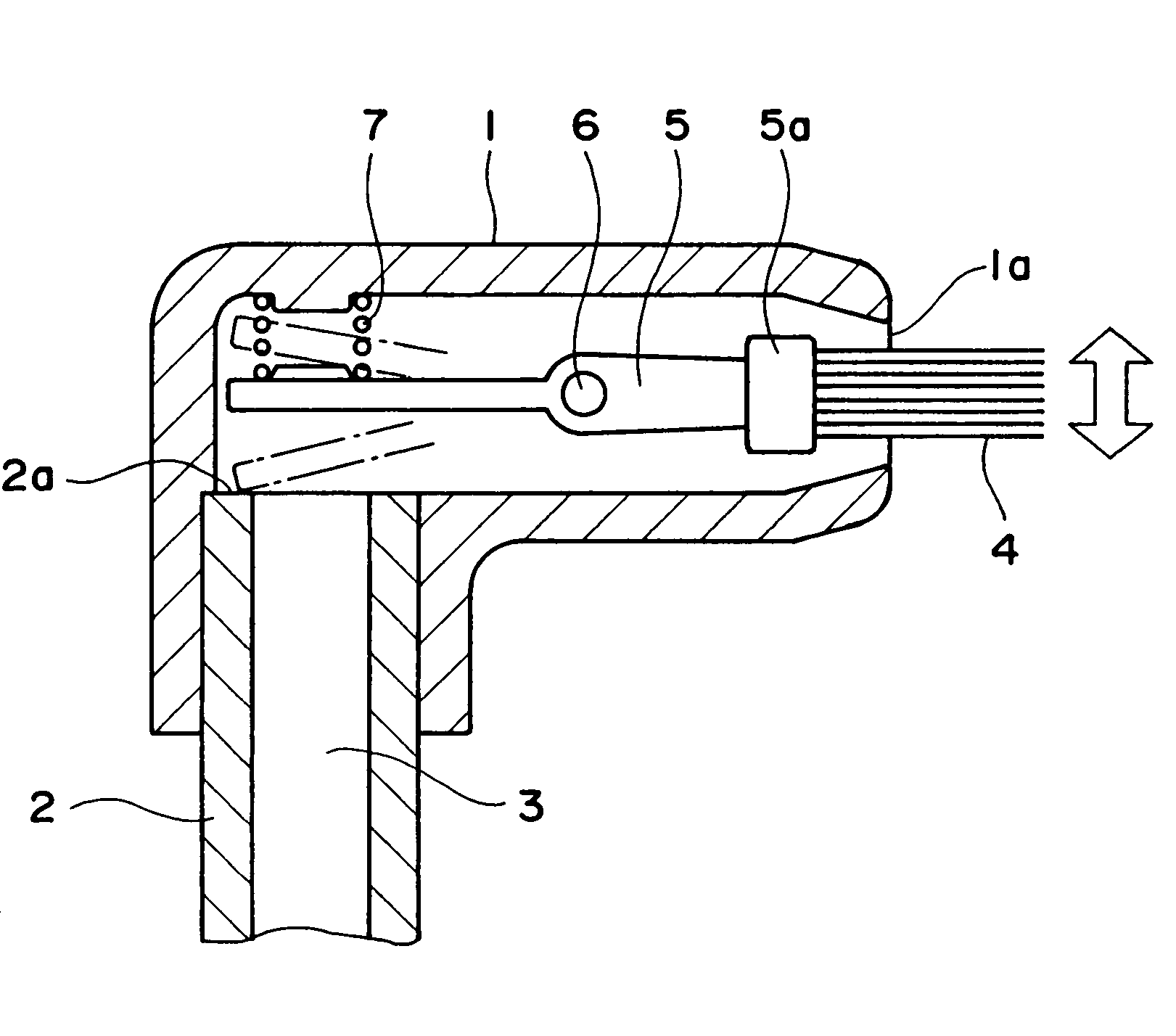
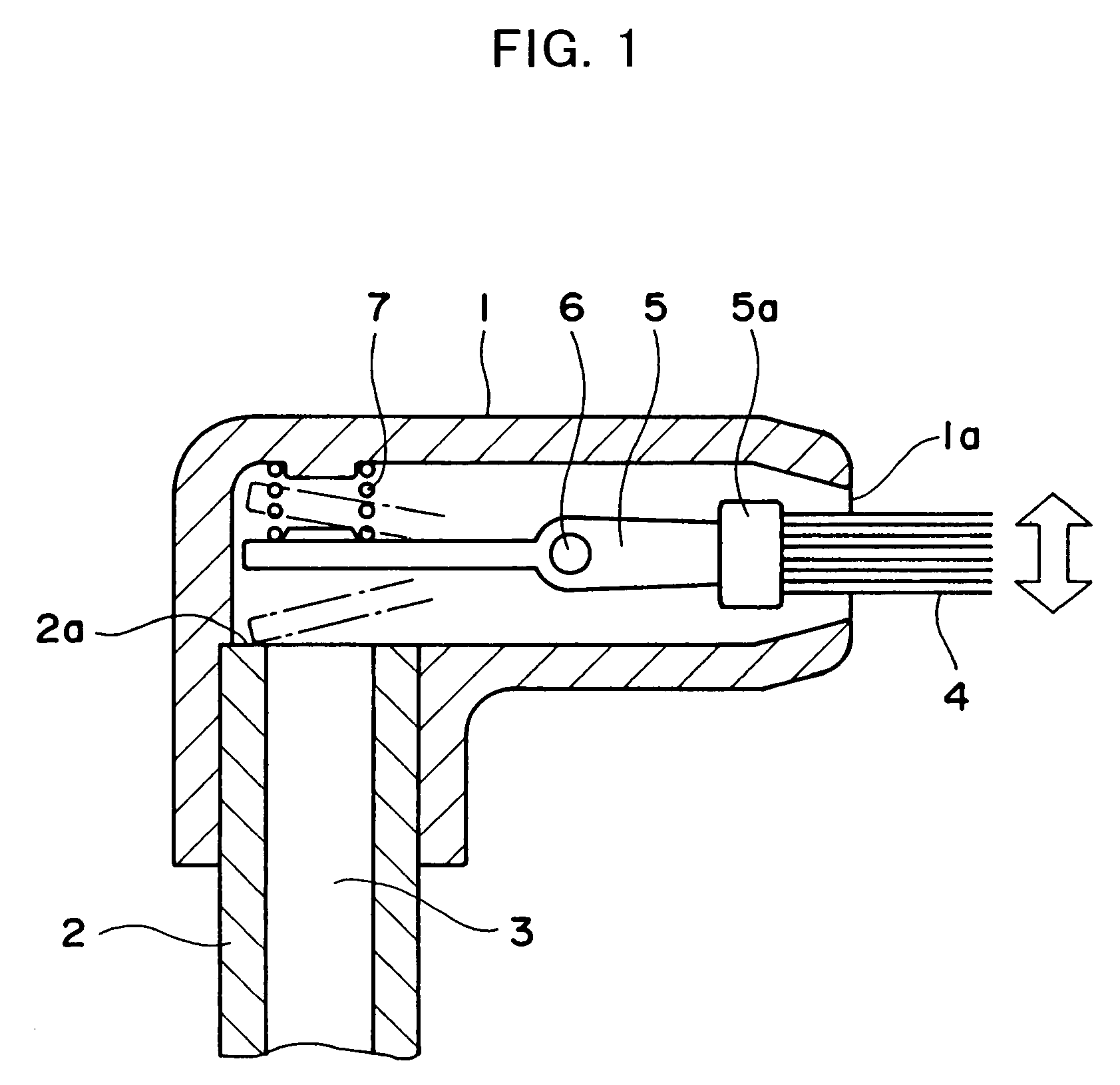
[0019]FIG. 1 illustrates the invention, i.e., an embodiment of the invention of claim 1. A nozzle 1 is secured to an end of a main body 2 nearly at right angles therewith, and a flow passage 3 leads to a blow-out port 1a open at an end of the nozzle 1 while being bent nearly at right angles as it goes to the blow-out port 1a from the main body 2.

[0020]Inside the nozzle 1, a brush lever 5 holding a brush 4 at an end core 5a is rotatably supported at its middle portion by a pin 6. The brush 4 is partly protruding maintaining a sufficiently large gap relative to the blow-out port 1a. On the side opposite to the brush 4, a compression coil spring 7 is acting on the rear potion of the brush lever 5, the compression coil spring 7 being a resilient member with its one end being secured to the inner wall surface of the nozzle 1. The rear portion of the brush lever 5 is urged in a direction against the flow of water from the main body 2 due to the compression coil spring 7.

[0021]According to...

second embodiment

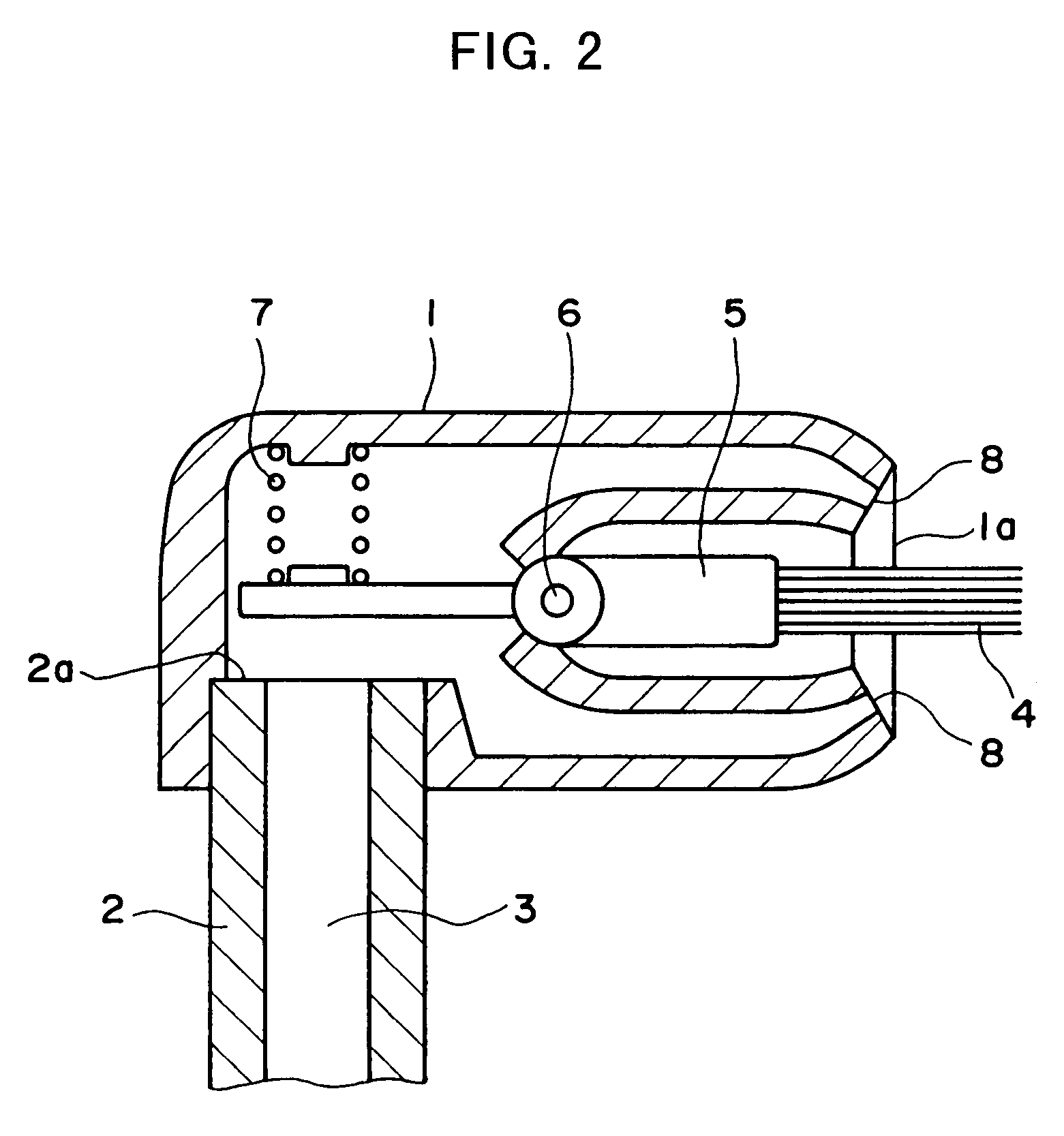
[0022]FIGS. 2 and 3 illustrate the invention, i.e., an embodiment of the invention of claim 2. In this embodiment, the opening 1a at the end of the nozzle 1 is not for blowing out the water but is simply for permitting the brush 4 to protrude in contrast with the structure of FIG. 1. Instead, a plurality of blow-out ports 8 are formed to surround the opening 1a. Water from the flow passage 3 flows being branched into these blow-out ports 8 and is blown out simultaneously being directed to the end of the brush 4.

third embodiment

[0023]FIGS. 4 and 5 illustrate the invention, i.e., an embodiment of the invention of claim 3. This embodiment uses a brush rotary shaft 9 holding the brush 4 at an end core 9a instead of the brush lever 5. A middle portion of the brush rotary shaft 9 is supported by a bearing 10 in the nozzle 1, and a rear end thereof is supported by a bearing in a recessed portion 11 in the wall in the nozzle, so that the brush rotary shaft 9 rotates being deviated by a distance L from the center axis of the flow passage 3 in the main body 2. A water-wheel 12 is secured to the brush rotary shaft 9 so as to receive the pressure of water flowing from the main body 2.

[0024]According to the structure shown in FIGS. 4 and 5, the water-wheel 12 receives the pressure of water flowing through the flow passage 3 in a deviated state. Therefore, the brush 4 rotates together with the brush rotary shaft 9 while water is blown out from the blow-out port 1a. In this case, the rotary motion can be converted into ...


PUM


Abstract

A safe brushing is realized without sticking the gum if the bristle tips are once inserted in a pocket of a tooth by using a system having a brush of which the bristle tips automatically vibrate in a direction at right angles with the direction of length of the bristles. A brush lever 5 having a brush 4 is swingingly supported in the nozzle 1, a flow passage 3 leading to a blow-out port 1a at an end of a nozzle 1 is partly bent, and a resilient member 7 is provided at the bent portion to urge the brush lever 5 in a direction opposite to the direction of flow of water, so that the brush lever 5 oscillates reciprocally due to the resilient force produced by the resilient member 7 and the pressure of water flow, causing the bristle tips of the brush 4 to oscillate in a direction at right angles with the direction of length of the bristles outside the nozzle 1.

Description

TECHNICAL FIELD[0001]The present invention relates to a tooth-brushing device suited for the prevention and therapy of pyorrhea alveolaris and decayed teeth by conducting the brushing using a brush protruded beyond a nozzle while blowing out water from a blow-out port of the nozzle.BACKGROUND ART[0002]It has been widely known that sordes on teeth are difficultly removed from such portions as gum grooves among the teeth and pockets deep in the gum grooves. In order to remove sordes on teeth, in general, attempts have been made to conduct the brushing by so contriving the shape of bristle tips of a tooth brush that the bristles can be easily inserted in the gum grooves. With this method, however, a persevering manual work must be conducted for every portion requiring a brushing time of not less than one hour, and a person finds himself tired on his arm consuming too much time and finds it not easy to continue the work any longer.[0003]To solve this problem, Japanese Patent No. 2663213...

Claims


Application Information

Patent Timeline
Patent Type & Authority Patents(United States)
IPC IPC(8): A61C17/02A61C3/03A46B11/06A61C17/00A61C17/22A61C17/30A61C17/38
CPCA61C17/38A61C17/30A46B13/06
Inventor ITO, KAZUMASATAKEDA, NOBUHIRO
Owner RICOH ELEMEX CORP
Why Eureka
Try Eureka