Surgical stapling device and method

a stapling device and surgical technology, applied in the field of surgical stapling devices and methods, can solve the problems of expensive professional time and discomfort of the patient, and achieve the effect of bringing about haemostasis in a short time and increasing the surface area

Inactive Publication Date: 2006-03-07
ABBOTT CARDIOVASCULAR
View PDF79 Cites 1534 Cited by
  • Summary
  • Abstract
  • Description
  • Claims
  • Application Information

AI Technical Summary

Benefits of technology

[0012]The staple and cap combination has the effect of bringing the two sides of the central opening together and

Problems solved by technology

The procedure can also be uncomfortable for the patient and invo

Method used


Image

  • Surgical stapling device and method
  • Surgical stapling device and method
  • Surgical stapling device and method

Examples


Embodiment Construction

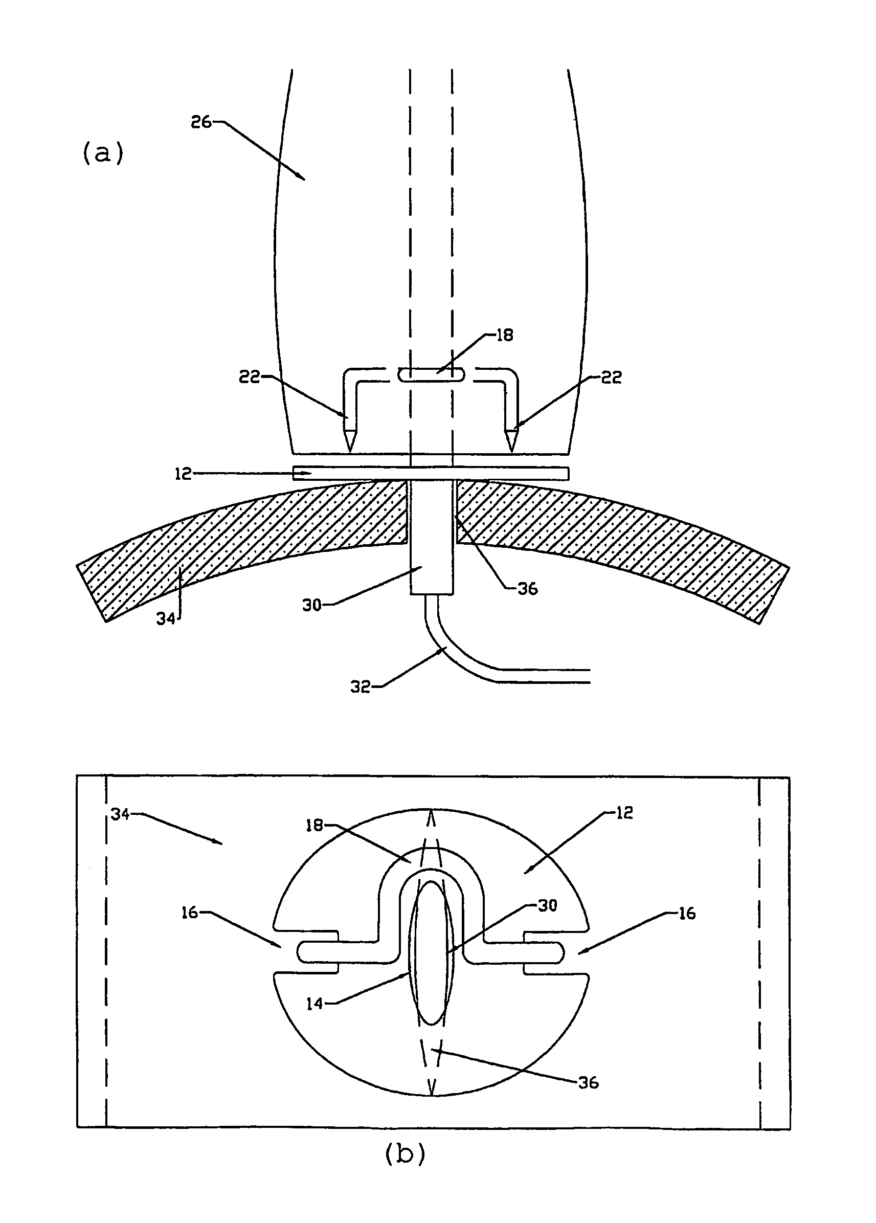
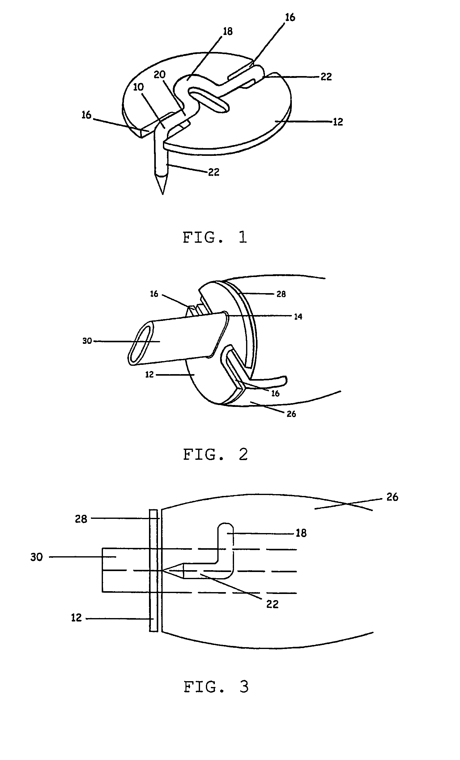
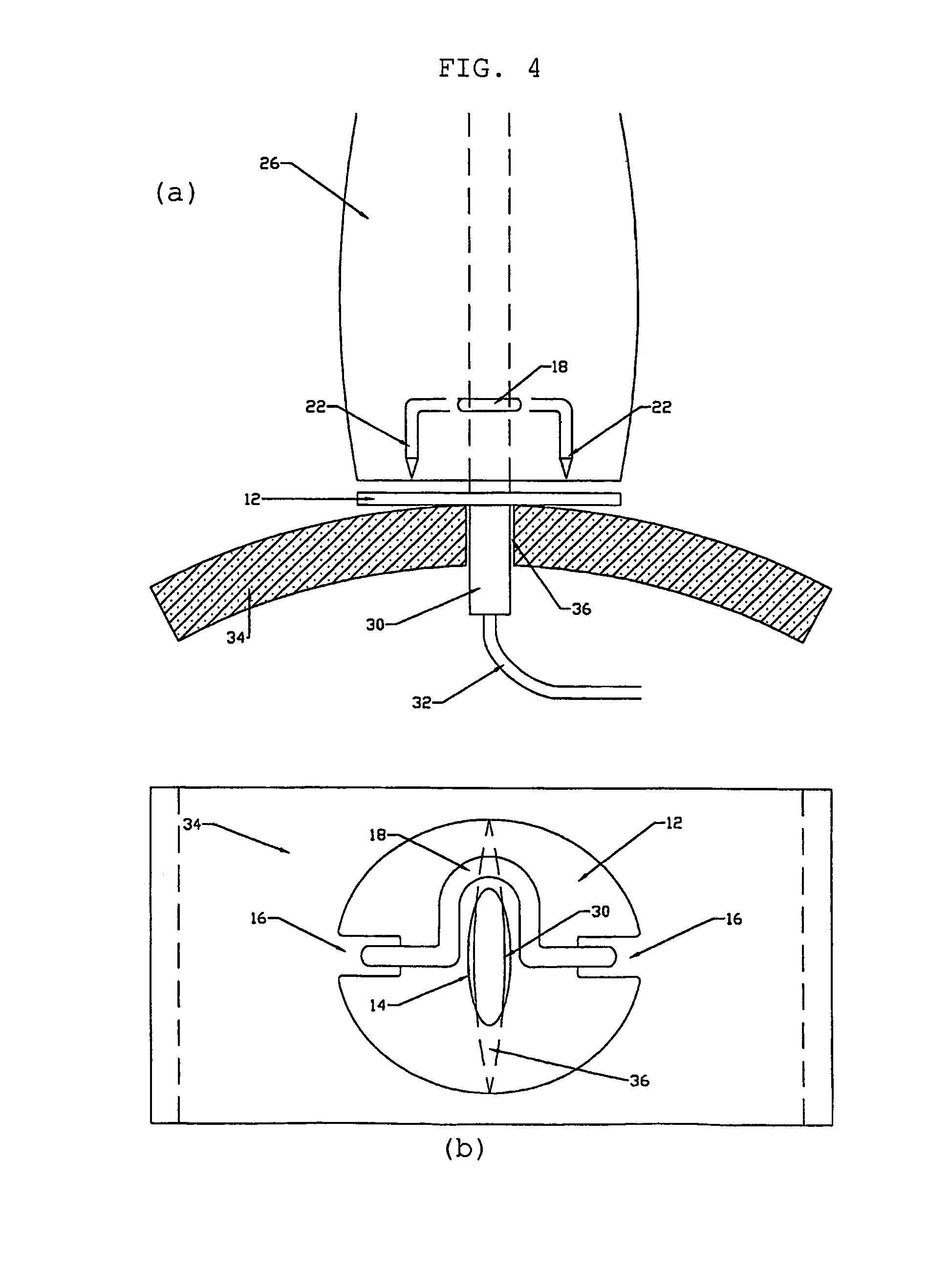
[0018]FIG. 1 shows a preferred surgical staple 10 and cap or cover 12 for use in the embodiment. The staple 10 is a generally U-shaped staple identical to that described in Irish Patent Application S2000 / 0722. The cap 12 is a generally circular flat deformable disk with a generally oval central opening 14 and two diametrically opposite generally U-shaped slots 16 extending radially inwardly from the periphery of the disk. The dimensions of the oval opening 14 are substantially the same as the external dimensions of an oval cross-section blood locator tube 30 (FIG. 2), and the major axis of the oval opening 14 is substantially normal to the direction of closure of the staple legs 22.

[0019]The disk 12 is constructed from a soft malleable biocompatible metal such as Titanium or a semi-flexible material such as Dacron, Hydrogel, Collagen or Cellulose, or other biocompatible material such as PLA, PGA or PLGA. When the staple 10 is positioned against the disk 12 in use, the hump 18 in the...


PUM


Abstract

A surgical stapling device is provided having an elongate housing and a surgical staple slidable longitudinally within the housing towards a free forward end thereof, the staple having a back and two forwardly pointing legs. The housing contains a staple-firing mechanism for driving the staple towards the free end of the housing, bending the staple to bring the free ends of the legs towards one another to close the staple, and releasing the closed staple. A cap is located at the free end of the housing at a position where, in operation of the staple-firing mechanism, the cap becomes trapped between the back of the closed staple and human or animal tissue being stapled so as to provide a greater area of pressure on the tissue than in the absence of the cap.

Description

CROSS-REFERENCE TO RELATED APPLICATIONS[0001]This application is a continuation application of International Application No. PCT / IE02 / 00118, filed Aug. 8, 2002, entitled “Surgical Stapling Device and Method,” which designated the United States and was published in the English language, and which claims priority to Ireland Application No. 010748, filed Aug. 9, 2001, entitled “Surgical Stapling Device and Methods.” These applications are expressly incorporated by reference herein.[0002]This invention relates to a surgical stapling device and method of surgical stapling.BACKGROUND OF THE INVENTION[0003]When performing catheterisation procedures, such as angiography or angioplasty, a catheter is generally introduced into the vascular system by first penetrating the skin, underlying tissues and blood vessel with a sharpened hollow needle. Next, a guidewire is commonly inserted through the lumen of the hollow needle and is caused to enter the selected blood vessel. Subsequently the needle...

Claims


Application Information

Patent Timeline
IPC IPC(8): A61B17/10A61B17/068A61B17/00A61B17/064
CPCA61B17/0057A61B17/0644A61B17/0682A61B2017/00672A61B2017/00663A61B2017/00668A61B2017/00637
Inventor CUMMINS
Owner ABBOTT CARDIOVASCULAR
Why Eureka
Try Eureka