Submerged ammonia removal system and method

Active Publication Date: 2006-03-07
UNIV OF UTAH RES FOUND
View PDF38 Cites 16 Cited by
  • Summary
  • Abstract
  • Description
  • Claims
  • Application Information

AI Technical Summary

Benefits of technology

[0017]It has been recognized that it would be advantageous to develop a simple and reliable system and method for removing ammonia from water, such as wastewater.
[0019]In accordance with a more detailed aspect thereof, the present invention provides a system for reducing the content of ammonia in wastewater. The system provides a surface that is substantially submerged in the wastewater, is aligned in a substantially non-vertical orientation, is substantially shielded from sunlight, and has a bio-film of nitrifying bacteria thereon. The system also includes an aeration system, configured to release air bubbles at a lower extremity of the submerged surface, such that the air bubbles travel along the submerged surface as they rise to create aerobic conditions at the bio-film, and such that the wastewater is circulated along the submerged surface.
[0020]In accordance with another aspect of the present invention, the invention provides a method for reducing the content of ammonia in water, comprising the steps of providing a submerged surface having a bio-film of nitrifying bacteria thereon, creating air bubbles that travel along the surface as they rise to create aerobic conditions on the surface, and contacting the water along the surface to allow the nitrifying bacteria to remove ammonia from the water.

Problems solved by technology

Wastewater treatment lagoons are one of the most widespread treatment technologies in the United States, and quite possibly one of the most neglected.
One disadvantage of most types of lagoon systems is their inability to remove ammonia compounds from the water.
Ammonia is the primary cause of stench and subsequent neighbor complaints from lagoon systems.
Ammonia is not removed from the wastewater stream in lagoons because the growth of nitrifying bacteria is not encouraged.
The primary disadvantages of a trickling filter are the initial capital costs to build the filter, pumping costs to lift the wastewater plus recycle to the top of the filter, maintenance of the mechanical distribution system at the top of the filter, and ultimate disposal replacement of the media within the filter.
Capital costs to reach the equivalent surface area of a trickling filter can be quite high, although the energy costs to rotate the devices are generally a fraction of the pumping costs for trickling filters.
The bottom of the lagoon does not provide surface area because it is unconsolidated media and is anoxic.

Method used


Image

  • Submerged ammonia removal system and method
  • Submerged ammonia removal system and method
  • Submerged ammonia removal system and method

Examples


Embodiment Construction

[0040]Reference will now be made to the exemplary embodiments illustrated in the drawings, and specific language will be used herein to describe the same. It will nevertheless be understood that no limitation of the scope of the invention is thereby intended. Alterations and further modifications of the inventive features illustrated herein, and additional applications of the principles of the inventions as illustrated herein, which would occur to one skilled in the relevant art and having possession of this disclosure, are to be considered within the scope of the invention.

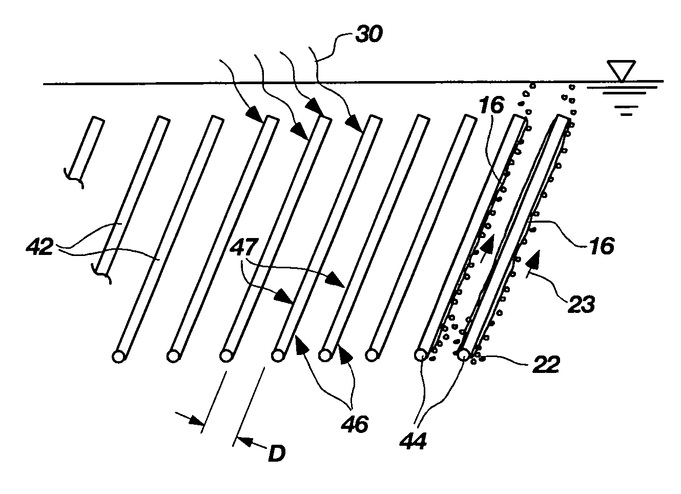
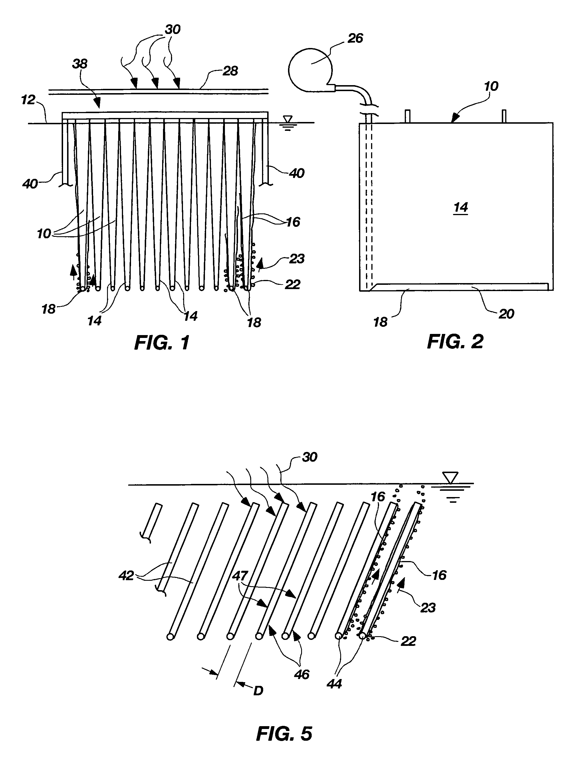
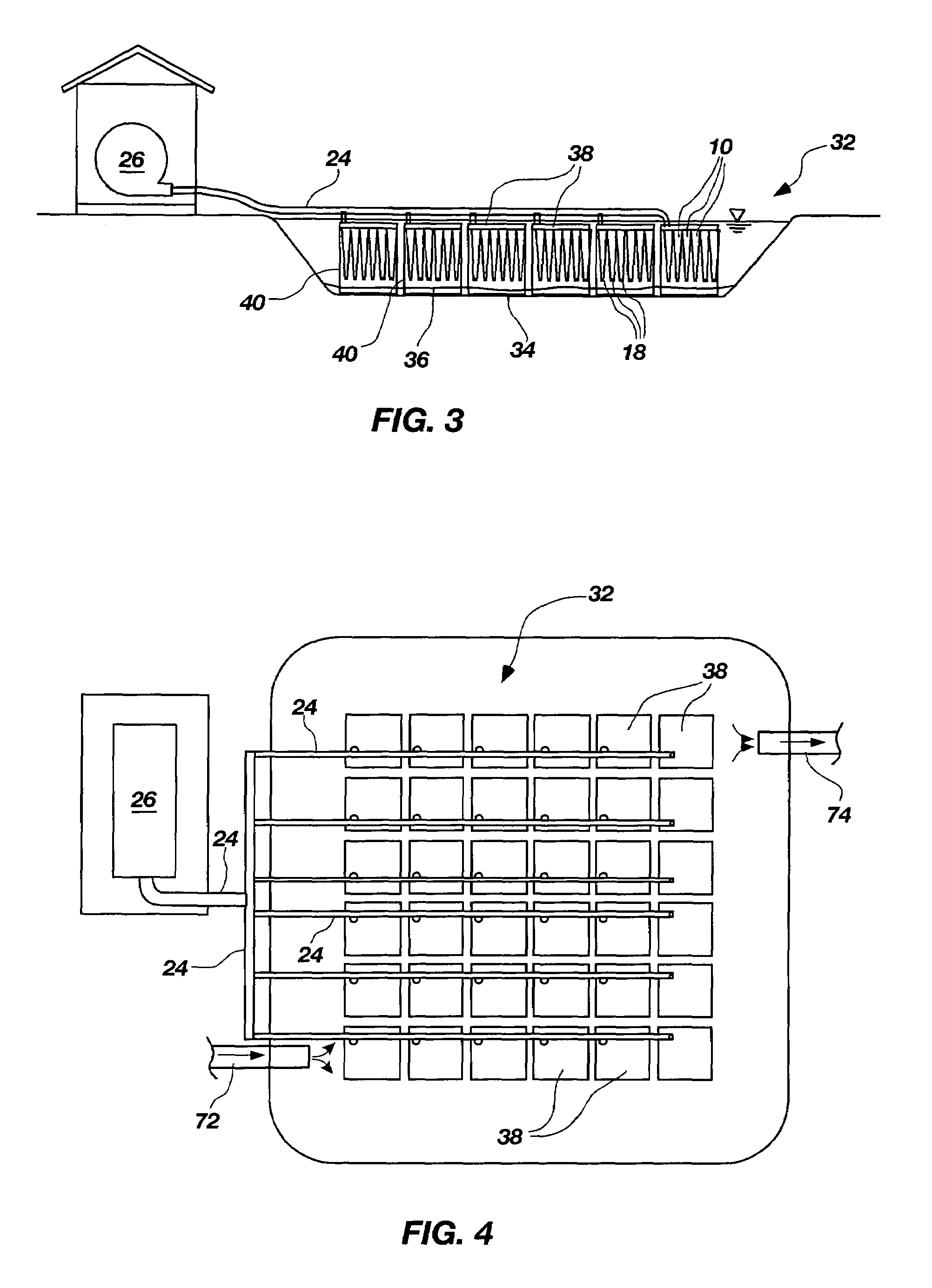
[0041]The present invention provides a simple and effective system and method for removing ammonia from water. The system can be used to enhance the performance of wastewater treatment lagoons, or other applications. The system operates through the addition of specially designed submerged structures that encourage the growth of a bio-film of certain types of nitrifying bacteria. The inventors have recognized that...


PUM

PropertyMeasurementUnit
Lengthaaaaaaaaaa
Angleaaaaaaaaaa
Shapeaaaaaaaaaa

Abstract

A system and method for reducing the content of ammonia in water provides a submerged surface having a growth of nitrifying bacteria thereon. An aeration system creates air bubbles that travel along the surface as they rise to create aerobic conditions on the surface, and to circulate the water along the surface to allow the nitrifying bacteria to remove ammonia from the water.

Description

CROSS REFERENCE TO RELATED APPLICATIONS[0001]This application claims priority to U.S. provisional patent application No. 60 / 470,280 filed May 14, 2003 and entitled AERATED SUBMERGED BIO-FILM FOR WASTEWATER TREATMENT LAGOON ENHANCEMENT.FEDERAL RESEARCH STATEMENT[0002]This invention was made with support from the United States Government, and the United States Government may have certain rights in this invention pursuant to USDA SBIR Grant (Proposal 2002-00234).BACKGROUND OF THE INVENTION[0003]1. Field of the Invention[0004]The present invention relates generally to water treatment. More particularly, the present invention relates to a system and method for removing ammonia from water, such as wastewater.[0005]2. Related Art[0006]Wastewater treatment lagoons are one of the most widespread treatment technologies in the United States, and quite possibly one of the most neglected. Lagoons as a treatment technology are suited for small to medium sized rural communities, animal feedlot ope...

Claims


Application Information

Patent Timeline
IPC IPC(8): C02F3/06B01D
CPCC02F3/101C02F3/20Y10S210/903C02F2103/007C02F2101/16Y02W10/37Y02W10/10
Inventor JOHNSON, KRAIGREAVELEY, LAWRENCE D.CHOI, YOUNGIK
Owner UNIV OF UTAH RES FOUND
Why Eureka
Try Eureka