Multiple channel ballast and networkable topology and system including power line carrier applications

a multi-channel ballast and networkable topology technology, applied in the field of multi-channel ballast and networkable topology and system including power line carrier applications, can solve the problems of inability to provide adequate and cost effective solutions in the existing plc communication system, and inability to meet the needs of lighting equipment, etc., to achieve the effect of extending the lamp life, ensuring safety, and ensuring the safety of equipmen

Inactive Publication Date: 2006-03-07
S T L ENERGY SOLUTIONS & TECH
View PDF4 Cites 125 Cited by
  • Summary
  • Abstract
  • Description
  • Claims
  • Application Information

AI Technical Summary

Benefits of technology

[0006]A major advantage of the present invention over prior art is that the sense and the control of the lighting are made individually for each fixture in a MFEB system, or for each lamp (or for more than one lamp in series) within one fixture. In use with dimmable lights, the MFEB is also referred to as a MFDEB. The MFEB is a central power supply for a multiplicity of lamps located at remote lamp fixtures. A “multi-lamp ballast” is a single power supply that controls individually a multiplicity of lamps located in a lamp fixture together with the ballast. For both multi fixture and multi lamp ballasts, the power topology for the lamp driver can be either a known half bridge topology, a full bridge topology, a push-pull topology, or a novel “economical half bridge” power topology having one common high side (HS) switch and multiple low side (LS) switches (or vice versa), as described below. Other applications may have more than one common HS switch operating together with a number of LS switches (or vice versa). In all cases, the fine control of the light level is achieved by using the feedback of the lamps current for each fixture, or the current of the single lamp in case of a single fixture. Control of “one lamp in a fixture” may refer to one lamp or several lamps connected in series. In a preferred embodiment, the sensing of additional parameters (such as temperature, cathode voltage, light intensity etc.) can be performed in close loop to achieve maximum efficiency, light quality, and extended lamp life.
[0007]The successful implementation of this invention is made possible by the fact that the sensing is done at the level of the fixture in the case of the MFEB, or at the level of the lamp for a single fixture, thus providing a true close-loop control of the light level for each fixture / lamp. An important inventive feature of the present invention is the method of power transmission from the MFEB to the light fixture, and the accurate sensing and accurate transmission of the lamp current feedback signal. This feedback allows the accurate control of the light level, and results in a uniform light level output of all the light fixtures controlled by the MFEB. This contrasts with the prior art, in which the light output of the different fixtures controlled by a central ballast has large variations, which are unacceptable to the customer or user. This stems from the fact that in prior art, for remote control of remote fixtures, the feedback is taken locally in the ballast and / or is common to all the lamps operated by the ballast.
[0008]In case of a single fixture application, additional advantages regarding energy saving can be achieved by the individual control of the lamps (like switching Off one lamp instead of dimming all of the lamps). Another advantageous aspect of the MFEB of the present invention is the possibility to provide central ballast power levels ranging from 250 W to 1000 W and beyond. This allows for example to design lighting systems having nine or more fixtures, each fixture being at different distances of more than 10 meters from the central ballast. After studying the present invention, one will appreciate that the number of fixtures that can be controlled using the systems and methods provided, is in principle unlimited.
[0009]Another outstanding aspect of this invention is that the ballast controller can perform also the function of an emergency system, by using efficiently the dimming capability and the individual switch-Off of the fixtures (or of the lamps in case of one fixture), to provide energy-efficient lighting in case of mains failure.
[0010]Yet another outstanding aspect of this invention is that the ballast controller can switch off individually each one of the fixtures in a MFEB, or each one of the lamps in a single fixture application. Furthermore, the ballast controller can dim individually each one of the fixtures / lamps, and monitor individually each one of the fixtures / lamps against any safety hazard (by measuring the voltage of each fixture / lamp or by performing additional measurements as required), as would have been done at the level of a single fixture control.
[0011]Yet another outstanding aspect of the present invention is that the control system has bi-directional communication capability either by PLC communication or by dedicated wiring, or by RF or IR remote control for digital control from an external source. The PLC communication is preferably a DSSS communication, explained below. The wire communication can be either PLC-DSSS, CAN, DALI, RS-485, or Microlan.

Problems solved by technology

Existing PLC communication systems do not provide adequate and cost effective solutions to the control networks mentioned above.
The problem of controlling a number of fixtures or a number of lamps in one fixture by a single central ballast has been tackled for a long time by lighting engineers, with little success.
The drawback of this approach is that the parameter variations between the lamps, the wiring, and the components at the level of the fixture, produce light dispersions that are intolerable to the eye.

Method used


Image

  • Multiple channel ballast and networkable topology and system including power line carrier applications
  • Multiple channel ballast and networkable topology and system including power line carrier applications
  • Multiple channel ballast and networkable topology and system including power line carrier applications

Examples


application example

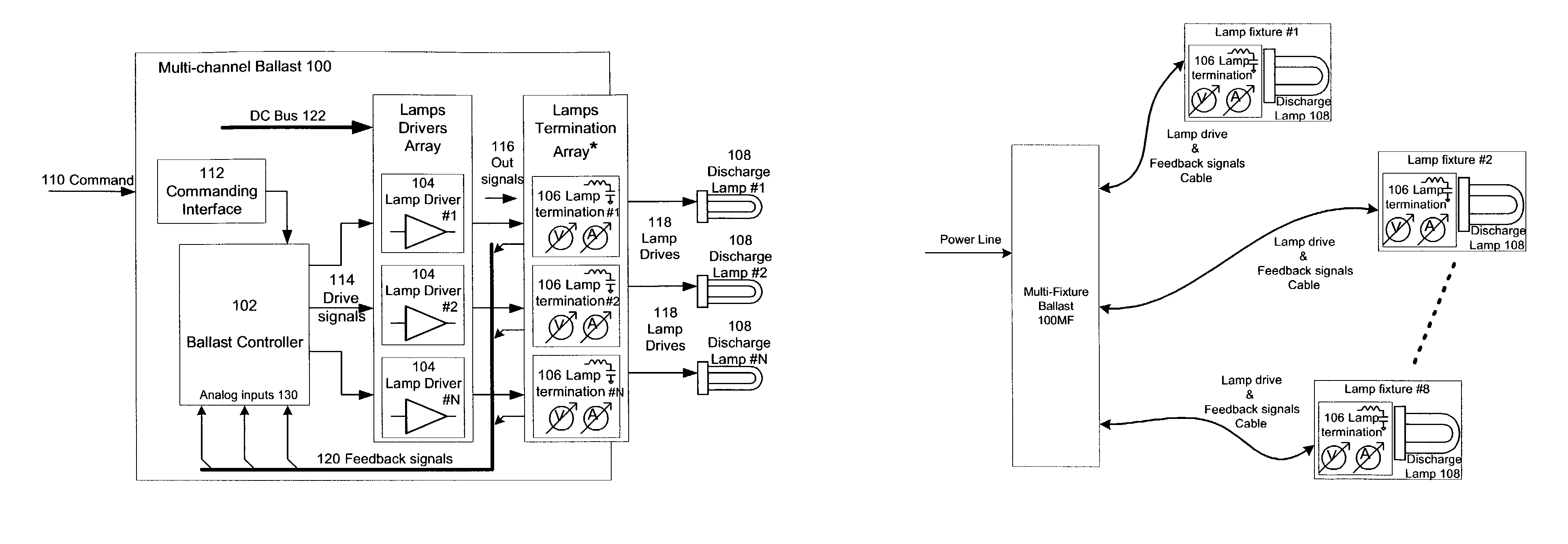
MLB 4 lamps True Parallel MLDEB Features

Brief Description

[0174]One Ballast drives 4 Lamps connected in true parallel[0175]Each lamp of the fixture can be remotely commanded On & Off[0176]Each Lamp is PLC addressable[0177]Each Lamp can be switched On or Off individually over the entire dimming range[0178]Stand-by power consumption, lamps off, typical 0.5–0.7 W[0179]Low THD (see previous Electrical Data Table)[0180]Low flicker (see previous Electrical Data Table)[0181]Complete PLC Modem, receives commands, transmits acknowledge and reports ballast and lamps status.[0182]Short Time to Market—Ballast designed for four T8 32W lamps. Using the PDK tool the ballast can be easily adapted to operate all linear and compact fluorescent lamps in the range of 17–42 W without compromising performance[0183]Startup behavior[0184]1. Practically no Glow currents at preheat: [0185]2. Starts up at any desirable light level: −1% to 100% without flash[0186]3. Start up at last light level—the ballast rem...


PUM


Abstract

Control systems and methods for independent control of power systems, particularly lighting network branches, and separate control of individual branch components. Multi-branch systems comprise independently controllable branches that inter-communicate via PLC communications. In each branch, components such as ballasts, local control units, sensors, actuators, and repeaters, may exchange commands and queries independently of a branch remote control unit (BRCU). Alternatively, a BRCU may manage or arbitrate communications, or interact with other BRCUs, other control units and external management systems. Ballasts include a multi-channel ballast that enables close-loop control of individual fixtures, or of individual dimmable or non-dimmable lamps within a fixture. The close-loop control is facilitated by sampling circuits / sensors co-located with each controlled fixture or lamp. All controllers are preferably implemented using an integrated digital controller. The PLC communication is preferably carried out by a direct spread spectrum method that eliminates side lobes from a cross-correlation function, using an anti-collision protocol.

Description

CROSS REFERENCE TO RELATED APPLICATIONS[0001]The present application claims the benefit of priority from U.S. Patent Application No. 60 / 384,410, filed Jun. 3, 2002, the contents of which are incorporated herein by reference.FIELD AND BACKGROUND OF THE INVENTION[0002]The present invention relates to systems and methods for control of power electronic applications, including their control over power lines by a CDMA (Code Division Multiple Access) DSSS (Direct Sequence Spread Spectrum) communication network, in particular for control system networks. The invention also relates to the control in close-loop of a number of lighting fixtures, or lamps within one fixture, by a single central ballast. The invention further relates to PLC (Power Line Carrier) communication control of large automation systems including HVAC (heating, ventilation, air-conditioning), security, fire alarm systems, etc. Existing PLC communication systems do not provide adequate and cost effective solutions to the ...

Claims


Application Information

Patent Timeline
Patent Type & Authority Patents(United States)
IPC IPC(8): G05F1/00H05B37/02
CPCH05B37/0263H03M1/129H05B47/185
Inventor MOGILNER, RAFAELNOGTEV, BORISKUCHLIK, YURIRUBIN, DANIELLEV, ARIERABINOVITZ, EYTAN
Owner S T L ENERGY SOLUTIONS & TECH
Why Eureka
Try Eureka