Compact bidirectional repeaters for wireless communication systems

a wireless communication system and bidirectional repeater technology, applied in the direction of radio transmission, submarine cables, transmission, etc., can solve the problems of repeater to be a typical unsatisfactory solution, significant circuit alterations, and insufficient communication links, so as to facilitate the realization of compact, reduce volume, and reduce the effect of siz

Active Publication Date: 2006-03-07
CALAMP CORP
View PDF21 Cites 46 Cited by
  • Summary
  • Abstract
  • Description
  • Claims
  • Application Information

AI Technical Summary

Benefits of technology

[0010]The present invention is directed to structures that facilitate the realization of compact (i.e., reduced volume) bidirectional repeaters for wireless communication systems. This reduction in size is achieved with repeater structures that include at least one of different-polarization antennas, back lobe suppressing structures, circuit feedback paths, antenna-feedback sensors, and automatic gain control.

Problems solved by technology

In these systems, situations often arise in which the client communication device is beyond an optimum communication range of the communication hub so that its communication link is not satisfactory or is completely inoperative.
However, it has generally been found that the downstream and upstream antennas must be separated by several signal wavelengths (e.g., as much as six feet) to reduce bidirectional feedback coupling between the antennas which otherwise initiates amplifier oscillation that disrupts communications rather than enhancing them.
The resultant size increase has caused repeaters to typically be an unsatisfactory solution.
In addition, signal repeaters have generally provided service only for a single communication channel and have required significant circuit alterations to accommodate different channels.

Method used


Image

  • Compact bidirectional repeaters for wireless communication systems
  • Compact bidirectional repeaters for wireless communication systems
  • Compact bidirectional repeaters for wireless communication systems

Examples


embodiment 80

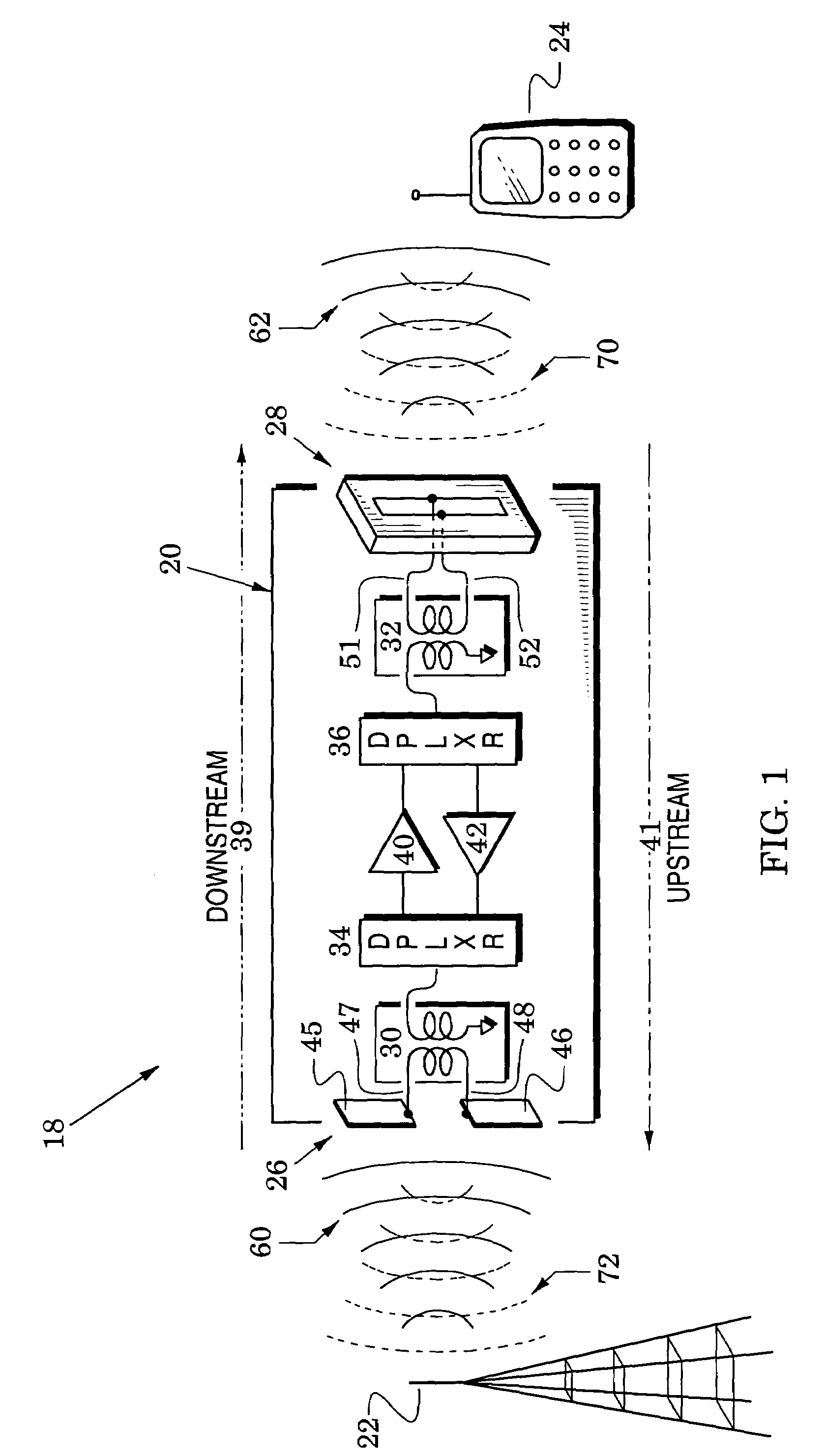
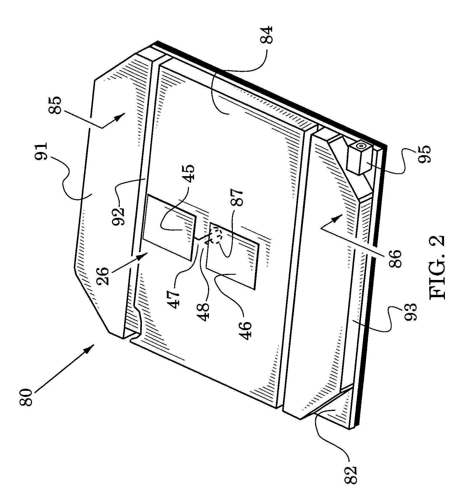
[0025]An embodiment 80 of the repeater 20 of FIG. 1 is shown in FIG. 2 which illustrates a circuit board 82, a conductive wall structure 84, and upper and lower chokes 85 and 86. The conductors 45 and 46 of the dipole antenna 26 of FIG. 1 are spaced above the wall structure 84 which serves both as a reflective ground plane for the dipole and as a shielding cover for downstream and upstream signal enhancing structures.

[0026]In particular, the first and second baluns 30 and 32, the first and second duplexers 34 and 36 and the downstream and upstream amplifier circuits 40 and 42 of FIG. 1 are carried on the circuit board 82 of FIG. 2 and positioned beneath the wall structure 84. The balanced transmission line 47 and 48 of FIG. 1 is fed through an aperture 87 in the wall structure 84 so that it can reach the first balun 30 which is below the wall structure.

[0027]In one embodiment, the dipole antenna 26 is spaced 0.25 wavelength above the wall structure, but other embodiments reduce the ...

embodiment 100

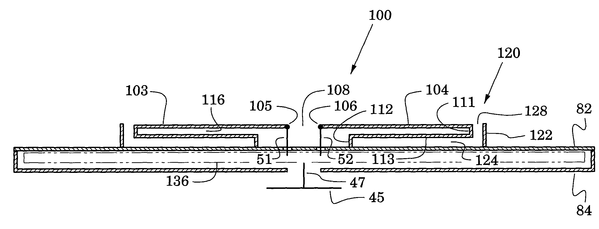
[0036]FIG. 3 is a perspective view of the other side of the repeater 80 of FIG. 2 and FIG. 4 is a sectional view along the plane 4—4 of FIG. 3. As described above with reference to FIG. 2, the repeater has a circuit board 82, a conductive wall structure 84, and upper and lower chokes 85 and 86 which are all indicated in FIGS. 3 and 4. An embodiment 100 of the horizontally-polarized slot antenna is also formed on this side of the repeater.

[0037]In particular, the slot antenna embodiment 100 is realized with a conductive member that is configured to form faces 103 and 104 that terminate in edges 105 and 106 that define a slot 108. The conductive member is further configured to form first and second walls 111 and 112 that are orthogonal to the faces 103 and 104 and that are connected together by a third wall 113 that is parallel to the faces 103 and 104. The first wall 111 is a continuation of the faces 103 and 104 and the second wall 112 is shorted to the conductive back of the circui...


PUM

PropertyMeasurementUnit
frequenciesaaaaaaaaaa
time delayaaaaaaaaaa
thicknessaaaaaaaaaa

Abstract

Compact bidirectional repeaters are provided for wireless communication systems. Their compact size is realized with repeater structures that include different-polarization antennas, back lobe suppressing structures, circuit feedback paths, antenna-feedback detectors, and automatic gain control.

Description

CROSS REFERENCES TO RELATED APPLICATIONS[0001]This application claims the benefit of U.S. Provisional Application Ser. No. 60 / 446,190 filed Feb. 10, 2003 and of U.S. Provisional Application Ser. No. 60 / 454,733 filed Mar. 13, 2003.BACKGROUND OF THE INVENTION[0002]1. Field of the Invention[0003]The present invention relates generally to signal repeaters for wireless communication systems.[0004]2. Description of the Related Art[0005]In a great number of wireless communication systems, communication signals flow between a central communication hub (e.g., a head end or base station) and a plurality of client communication structures or devices (e.g., a client personal communication system (PCS) or a client premises equipment (CPE).[0006]In these systems, situations often arise in which the client communication device is beyond an optimum communication range of the communication hub so that its communication link is not satisfactory or is completely inoperative.[0007]The communication ran...

Claims


Application Information

Patent Timeline
Patent Type & Authority Patents(United States)
IPC IPC(8): H01Q13/10H01B7/14H04B7/155H04B7/26
CPCH04B7/15571
Inventor HORNSBY, JAMES J.SANFORD, GARY G.KELKAR, KRISALEMAN, SHAWNUPADHYE, VISHWANAPH G.
Owner CALAMP CORP
Why Eureka
Try Eureka