
Self-calibrating, digital, large format camera with single or multiple detector arrays and single or multiple optical systems

a large-format camera and detector array technology, applied in the field of photogrammetry, can solve the problems of distorting the image, unable to see the doors, windows, roof lines, etc. of the house, and be unable to discern the individual house built on the side of the mountain, and achieve the effect of high resolution

Inactive Publication Date: 2006-03-07
VEXCEL IMAGING US INC
View PDF35 Cites 263 Cited by
  • Summary
  • Abstract
  • Description
  • Claims
  • Application Information

AI Technical Summary

Benefits of technology

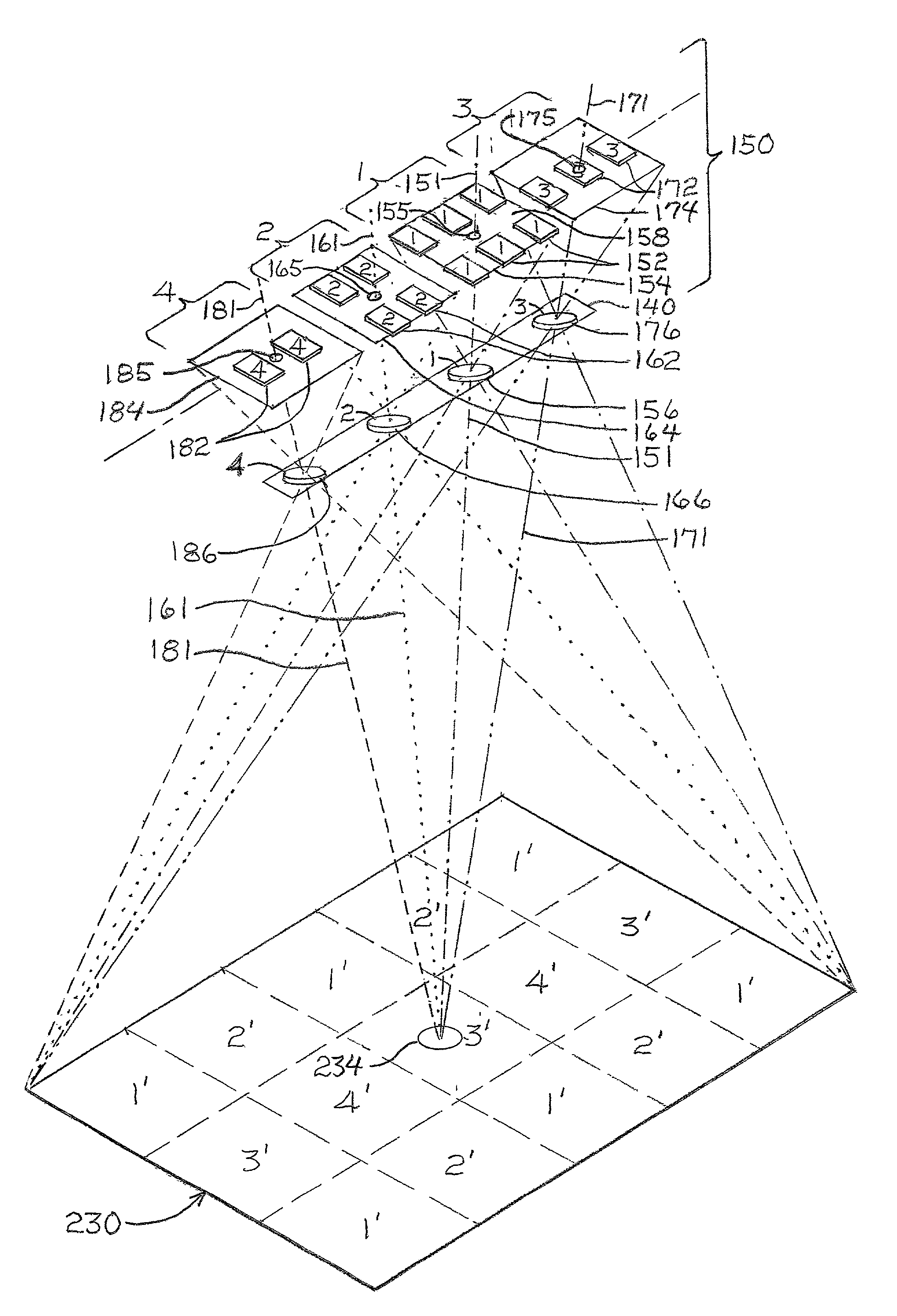
"The present invention provides a method and camera system for acquiring high resolution, large format, digital images of large area objects without the need for expensive and flawless detector arrays. The method involves exposing multiple portions or sub-areas of the object to overlapping sub-images, which are then pieced or stitched together to form a seamless macro-image with a single perspective center. The camera system can have multiple sub-cameras with different lens systems and detector arrays to capture the overlapping sub-images. The detector arrays can be larger to increase the format size without adding more sub-cameras. The method and camera system can produce color and near infrared images without the need for additional sub-cameras. The sub-image read-out from the various detector arrays is accomplished simultaneously in a parallel manner for speed."

Problems solved by technology

The resulting picture of the mountain, which, when processed and printed, can be held in a person's hand and pasted onto a page in a scrap book, may appear to be sharp and clear, but it may not be possible to discern an individual house built on the side of the mountain in the picture because the house is too small.
Expanding or “blowing up” the picture to a larger size might make it possible to discern the house, but it may still be impossible to see the doors, windows, roof lines, and other details of the house because the resolution of such fine details just might not be in the picture.
Such wide angle lenses, sometimes called“fisheye” lenses, are well-known, but they also distort the image—magnifying portions in the middle and diminishing marginal portions of the image.
Geometric resolution obtainable by digital cameras is also limited by the sizes of photodetector arrays.
Therefore, such signal output might enable one to discern that there is something in the resulting mountain picture where the house is located, but it would not be able to produce a recognizable house shape, much less details of doors, windows, roof lines, and the like.
Furthermore, no amount of enlargement or “blowing up” of the picture could produce more detail.
For example, if in taking an aerial picture of a city, all of the light reflected from a city block is focused on one photodetector, it may be possible to discern the block in the resulting picture, but it would not be possible to discern individual buildings, back yards, alleys, cars in driveways, and the like.
A problem faced by digital camera manufacturers is that large photodetector arrays, to the extent they are commercially available, are not inexpensive.
Therefore, most camera designers and manufacturers are limited to commonly available photodetector arrays.
Rectangular array sizes of about 1,000×1,000, i.e., about 1,000,000, photodetectors are now fairly common and readily available, while arrays of 5,000×5,000, i.e., about 25,000,000 photodetectors, or more are considered to be “large” and expensive.
Several high-end camera manufacturers do make digital cameras with 10,000×10,000 arrays, i.e., about 100,000,000 photodetectors, but the costs of such cameras are prohibitive fore most purposes.
Besides cost, there are other limitations of such “large” array digital camera, especially as compared to analog cameras using film, which can generally achieve better geometric resolution than conventional digital cameras.
For example, radiometric resolution, i.e., gray scale and / or color resolution, of analog film cameras generally not as good as that of digital cameras.
On the other hand, large arrays of photodetectors often have defective detector elements that produce defective images.
Also, their large size, and, especially the time it takes to read an image of a large array of photodetectors, are all significant problems.
The read-out time alone can reduce their usefulness to situations in which there is no movement between the object and the camera, because such movement before all the electric signals from all the photodetectors in the array that can be read could introduce distortions in the resulting picture or image.
Further, such large detectors for large format photogrammetry applications have to be nearly flawless, i.e., few, if any, bad photodetectors, because there is no redundancy, and bad photodetectors in the array will leave flaws in images being acquired by the detector array.
The requirement for such flawlessness puts further pressure on cost of such cameras.
Other methods to overcome these limitations for acquiring larger format images of large area objects, such as macro- and micro-scanning cameras, also take time to create the image.
The problem with such “push-broom” scanning is that it is difficult to know the camera path accurately, which results in a notorious lack of accuracy in stereo measurements or menstruation in the resulting images.
As the aircraft or spacecraft flies over the object, each detector array produces a “push-broom” strip of imagery, but these “push-broom” strips are not geometrically independent, since the multiple image lines are collected simultaneously with the same camera.
A problem is that each image line has a separate perspective center, so the resulting composite image of the object has many perspective centers.
This system requires the motion of the airplane or spacecraft, and it cannot be used to image a moving object.
It also has the problem of multiple perspective centers.
A large-image format can be assembled from the sub-images, but accuracy can suffer because of differences among the multiple cameras, and it has the problem of multiple perspective centers—one for each camera.

Method used


Image

  • Self-calibrating, digital, large format camera with single or multiple detector arrays and single or multiple optical systems
  • Self-calibrating, digital, large format camera with single or multiple detector arrays and single or multiple optical systems
  • Self-calibrating, digital, large format camera with single or multiple detector arrays and single or multiple optical systems

Examples


Embodiment Construction

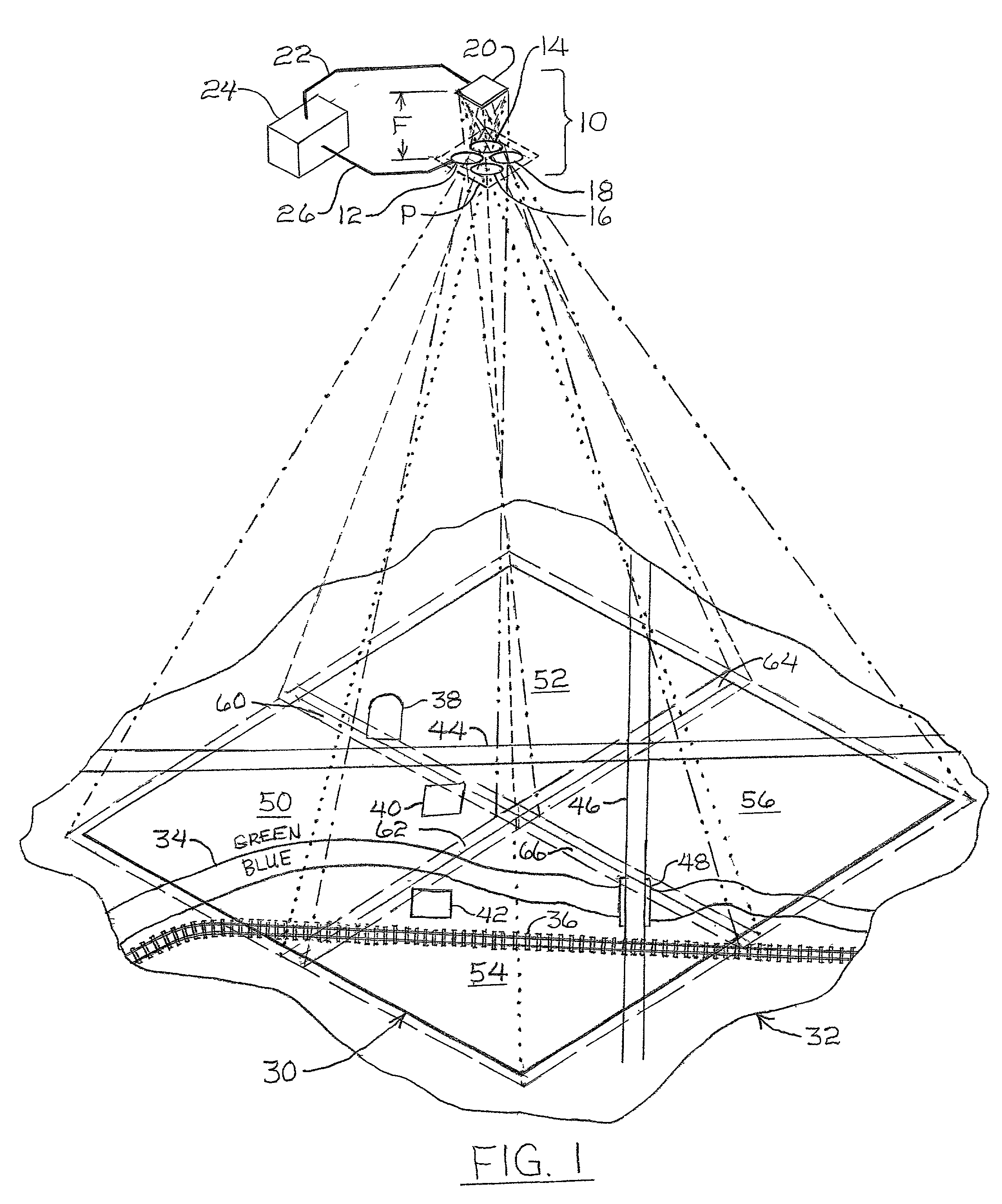
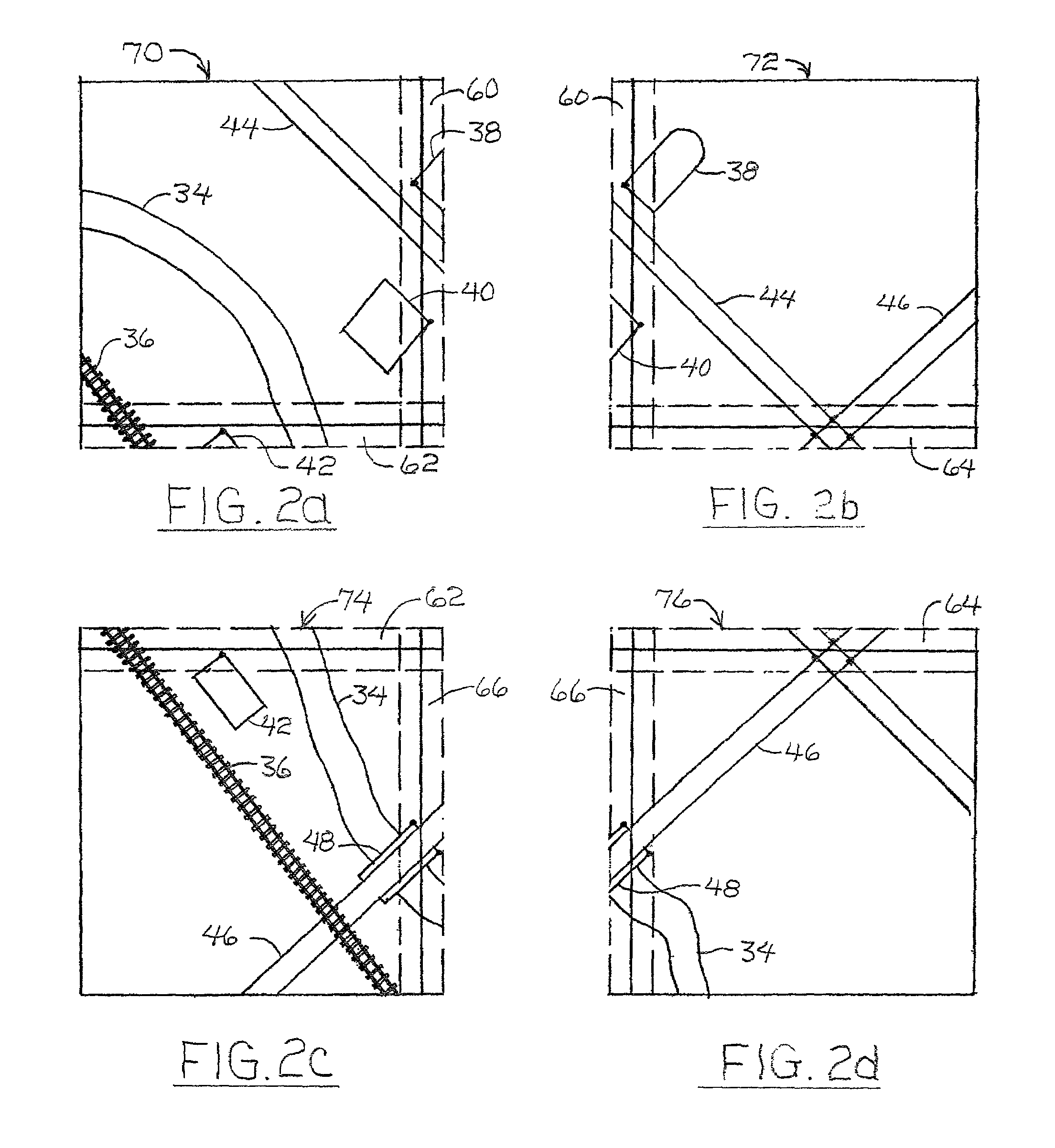
[0054]One of the simpler, yet effective, large format, digital camera systems of this invention is illustrated diagrammatically in FIG. 1. Essentially, the large area camera system 10 in FIG. 1 is represented by a plurality of lens systems 12, 14, 16, 18, all of which have the same focal length F and are positioned in a common plane P, and a photodetector array 20 positioned in the focal plane of the lens systems 12, 14, 16, 18, i.e., at a distance F from the plane P. The photodetector array 20 is connected electrically by suitable conductors 22 to a control circuit 24, which includes at least a microprocessor, input / output circuitry, memory, and power supply for driving the photodetector array 20, reading sub-image data out of the photodetector array 20, and storing such sub-image data. Other data processing functions, such as combining sub-images and / or image display functions, can be accomplished in the camera system 20 or with other peripheral data processing equipment.

[0055]The...


PUM


Abstract

Large format, digital camera systems (10, 100, 150, 250, 310) expose single detector arrays 20 with multiple lens systems (12, 14, 16, 18) or multiple detector arrays (104, 106, 108, 110, 112, 114, 116, 118, 120, 152, 162, 172, 182, 252, 262, 272, 282, 322, 324) with one or more single lens systems (156, 166, 176, 186) to acquire sub-images of overlapping sub-areas of large area objects. The sub-images are stitched together to form a large format, digital, macro-image (80, 230″, 236″, 238″, 240″), which can be colored. Dampened camera carrier (400) and accelerometer (404) signals with double-rate digital signal processing (306, 308) are used.

Description

REFERENCE TO RELATED APPLICATION[0001]This is a nonprovisional patent application based on the provisional patent application No. 60 / 289,008, filed in the U.S. Patent and Trademark Office on May 4, 2001.BACKGROUND OF THE INVENTION[0002]1. Technical Field[0003]This invention is related generally to photogrammetry and more specifically to large format digital cameras for acquiring images of large area objects or large areas of large objects, such as aerial images of portions of the surface of the earth.[0004]2. Background Art[0005]It is often desirable to photograph or otherwise acquire digital images of large areas of objects, but in large formats to enhance geometric resolution, i.e., ability to distinguish geometric details for visual inspection or analysis. For example, it is easy to get a picture of a mountain with a digital camera by backing far enough away from the mountain until the entire mountain fits within the field of view of camera lens, set the focus at infinity, and pu...

Claims


Application Information

Patent Timeline
Patent Type & Authority Patents(United States)
IPC IPC(8): G06K9/32H04N1/387H04N5/225H04N7/18H04N9/097G01C11/02H04N23/16
CPCG06T3/4038G01C11/02
Inventor GRUBER, MICHAEL A.LEBERL, FRANZ W.PONTICELLI, MARTIN
Owner VEXCEL IMAGING US INC
Learn More