
Optimal elements (such as vari focal lens component, vari-focal diffractive optical element and variable declination prism) and electronic image pickup unit using optical elements

a technology of optical elements and optical elements, applied in the field of optical elements, can solve the problems of low utilization efficiency of light, complicated mechanical structure, and low efficiency of light utilization, and achieve the effect of excellent versatility and enhanced light utilization efficiency

Inactive Publication Date: 2006-03-07
OLYMPUS CORP
View PDF15 Cites 202 Cited by
  • Summary
  • Abstract
  • Description
  • Claims
  • Application Information

AI Technical Summary

Benefits of technology

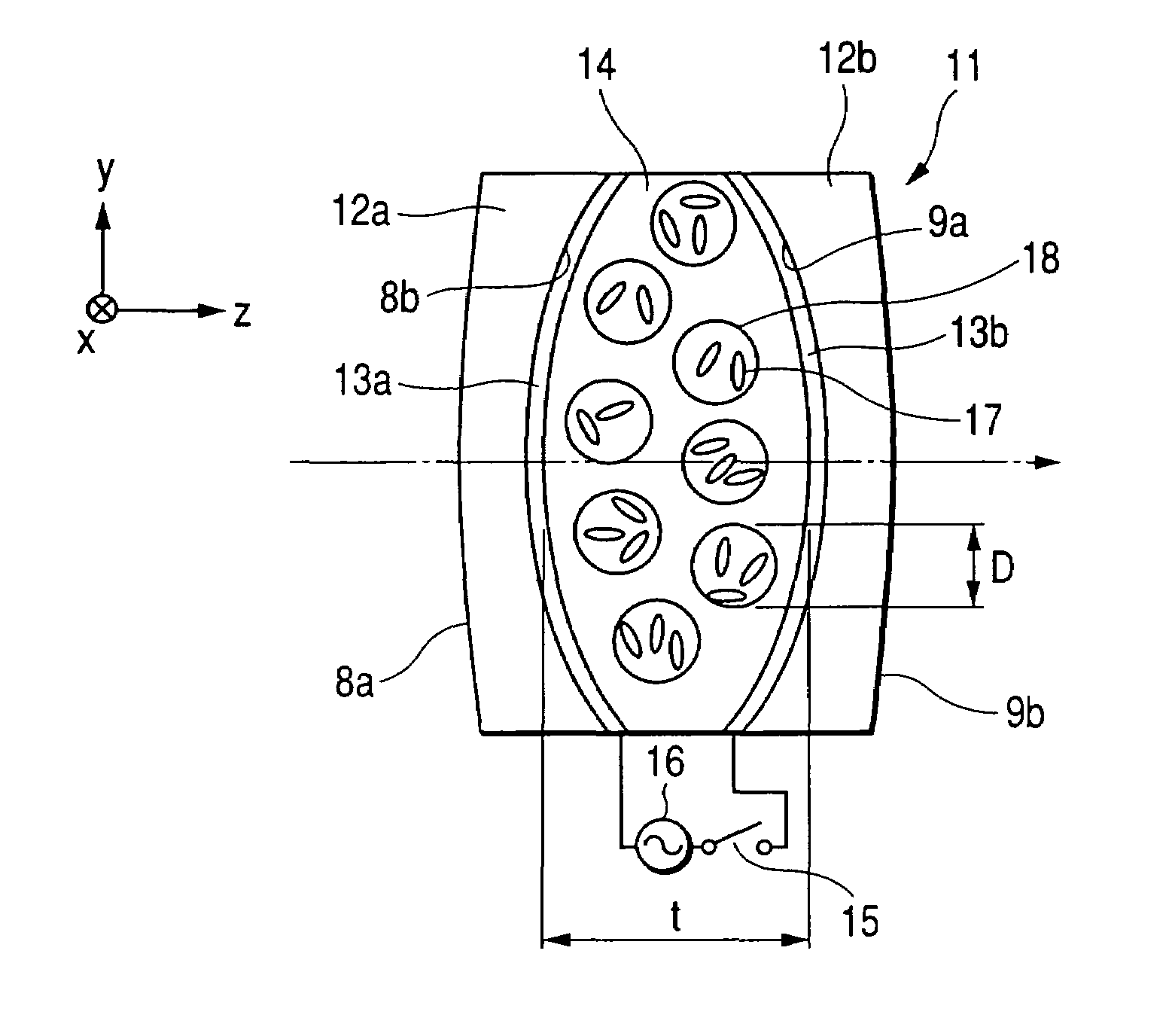
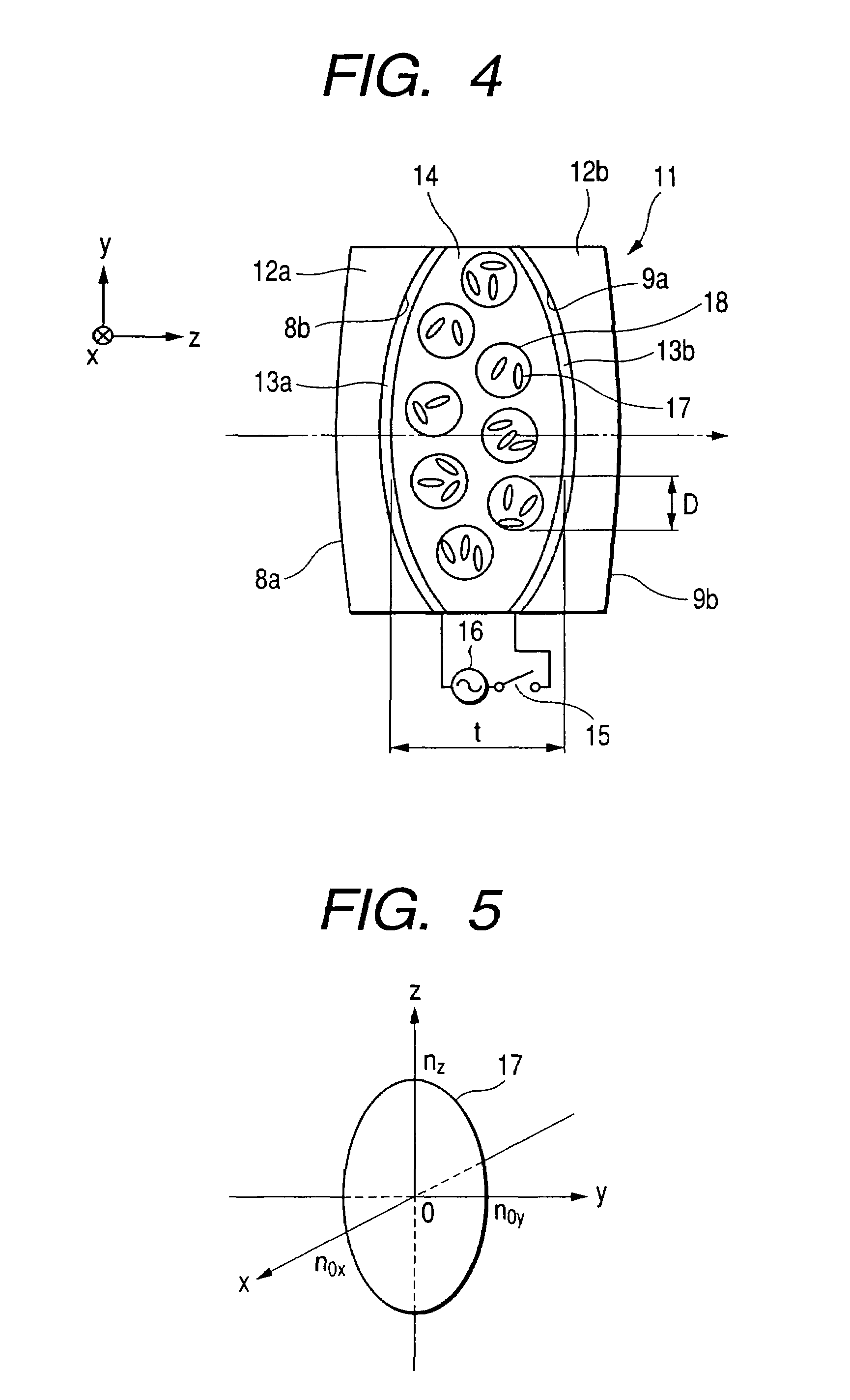
The present invention provides optical elements with variable optical characteristics, including vari-focal optical elements, vari-focal diffractive optical elements, vari-focal mirrors, and variable declination prisms. These optical elements have excellent versatility and can be used in various optical instruments. They enhance light utilization efficiencies and are easily applicable. The optical elements have a polymer dispersive liquid crystal layer that can change the focused point of rays or the declinations of rays by applying an electric field. The invention improves the performance of optical instruments and provides better optical quality.

Problems solved by technology

However, such a lens system has a drawback that it has a complicated mechanical structure.
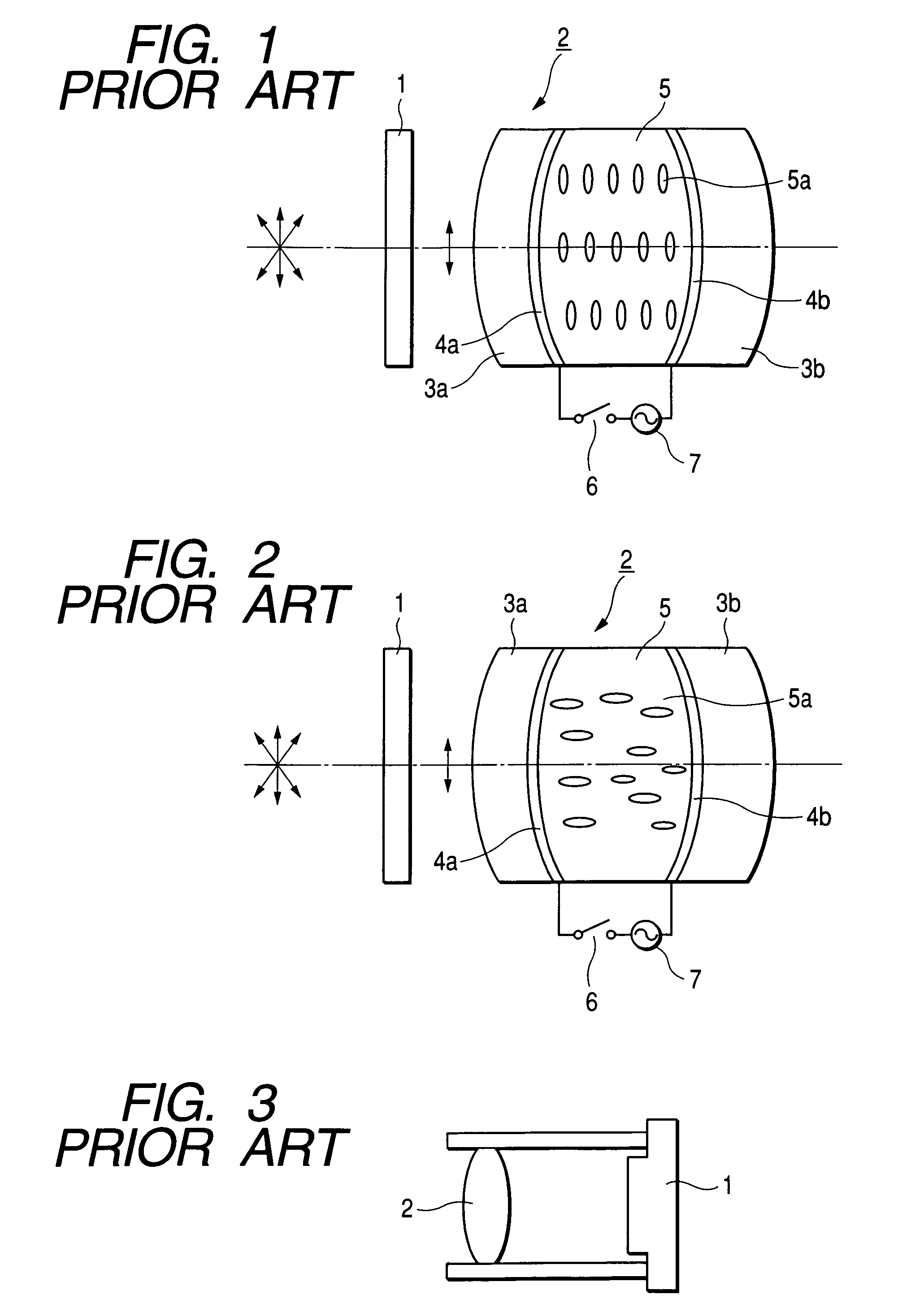
However, the optical system shown in FIG. 1 poses a problem that it attenuates rays to be incident on the liquid crystal lens component 2 during transmission through the polarizing plate 1 and lowers a light utilization efficiency since it requires to dispose the polarizing plate 1 before the liquid crystal lens component 2 so that only the predetermined linearly polarized component is incident on the liquid crystal lens component 2.
Further, the optical system which utilizes light at such a low efficiency poses another problem that it is applicable only to limited instruments or has a low versatility.
Such an electronic image pickup unit generally uses a lens system which has a relatively complicated composition, has a complicated configuration as a whole, comprises a large number of parts and requires tedious assembly, thereby being limited in compact design and reduction of a manufacturing cost thereof.

Method used


Image

  • Optimal elements (such as vari focal lens component, vari-focal diffractive optical element and variable declination prism) and electronic image pickup unit using optical elements
  • Optimal elements (such as vari focal lens component, vari-focal diffractive optical element and variable declination prism) and electronic image pickup unit using optical elements
  • Optimal elements (such as vari focal lens component, vari-focal diffractive optical element and variable declination prism) and electronic image pickup unit using optical elements

Examples


first embodiment

[0210]the image pickup unit according to the present invention is a plate-like image pickup unit 207 which is manufactured by forming, as shown in FIG. 51, free curved surfaces 204, 206 and a diffractive optical element (hereinafter referred to as DOE) 205 as optical elements on both surfaces of a transparent substrate 203 made of a glass, crystal, plastic or another material, and further forming a solid-state image pickup device 201 by using a thin silicon film technique or the like. A free curved surface is a kind of aspherical surface which is not always axially symmetrical but usable as a surface having a refractive or reflective function. In this embodiment, a ray Re coming from an object (not shown) is refracted by the free curved surface 204, deflected and reflected by the offaxis type DOE 205, reflected by the free curved surface 206, and imaged on the solid-state image pickup device 201. Since the free curved surfaces 204, 206 and the DOE 205 correct aberrations, an image w...

fourth embodiment

[0214]the image pickup unit according to the present invention is a plate-like image pickup unit which uses a reflection type vari-focal Fresnel mirror 222 as shown in FIG. 58. The Fresnel mirror 222 functions as a vari-focal Fresnel mirror since a reflecting surface 223 is disposed as shown in FIG. 59 and a refractive power of a Fresnel surface 226 is changed when a voltage is varied by turning on / off a switch 224 or with a variable resistor 225. A DOE may be used in place of the Fresnel surface 226.

[0215]A vari-focal DOE 217 and the Fresnel mirror 222 adopted for the fourth embodiment described above can be used not only in the plate-like image pickup unit 207 but also in ordinary image pickup units, vari-focal lens elements for optical disks having different thicknesses, electronic endoscopes, TV cameras, film cameras and so on as shown in FIG. 60. For changing focal length more speedily, it is more preferable to use tolane series liquid crystals, for example DON-605: N−1 prepare...


PUM

PropertyMeasurementUnit
mean diameteraaaaaaaaaa
sizesaaaaaaaaaa
distancesaaaaaaaaaa

Abstract

Optical elements such as a vari-focal lens element, a vari-focal diffractive optical element and a variable declination prism usable as spectacle lens elements and so on.

Description

CROSS REFERENCE TO RELATED APPLICATION[0001]This Application is a Divisional Application of U.S. application Ser. No. 09 / 092,651, filed Jun. 9, 1998, now U.S. Pat. No. 6,626,532, the specification and drawings of which are incorporated herein by reference.BACKGROUND OF THE INVENTION[0002]a) Field of the Invention[0003]The present invention relates to optical elements such as a vari-focal lens element, a vari-focal diffractive optical element and a variable declination prism which are to be used as liquid crystal optical elements. The present invention also relates to an electronic image pickup unit which uses these optical elements.[0004]b) Description of the Prior Art[0005]For composing a vari-focal lens system of lens elements which are manufactured by polishing a glass material, it is conventional to change a focal length of the lens system by moving a lens unit(s) in a direction along an optical axis, for example, as in a zoom lens system for cameras since the lens elements cann...

Claims


Application Information

Patent Timeline
Patent Type & Authority Patents(United States)
IPC IPC(8): G02F1/29G02C1/00G02C7/12G02C7/08G02C7/10G02C7/14
CPCG02C7/083G02C7/101G02C7/14G02F2001/294G02C2202/18G02C2202/20G02C2202/16G02F1/294
Inventor NISHIOKA, KIMIHIKOISHIZAKI, KOJIKABURAKI, MASAHIRO
Owner OLYMPUS CORP
Learn More