Optical coupling device and method for fabricating the same, and master used in fabricating optical coupling device and method for fabricating the same

a technology of optical coupling and master, which is applied in the field of optical coupling devices and masters used in fabricating optical coupling devices, can solve the problems of difficult system fabrication, large v-shaped groove length, and inability to generate optical coupling loss, etc., and achieve the effect of precise optical alignment and increased dynamic stability of optical fiber array

Inactive Publication Date: 2006-03-07
ELECTRONICS & TELECOMM RES INST
View PDF20 Cites 12 Cited by
  • Summary
  • Abstract
  • Description
  • Claims
  • Application Information

AI Technical Summary

Benefits of technology

[0009]Thus, the object of the present invention is to fabricate a multi-step metal master capable of increasing a dynamic stability of an optical fiber array by using a photoresist film for X-rays exposure and performing a precise optical alignment between a waveguide and a optical fiber, and provide an optical coupling device capable of solving the above-mentioned problem by fabricating a narrow-pitch multi-channel optical device by a hot embossing process using the master and a master used in fabricating the same.

Problems solved by technology

At this case, since the pitch between the channels is reduced from 250 μm to 125 μm, it is difficult to fabricate the system.
Accordingly, first, optical coupling loss can be generated due to the variation if a thermal or mechanical impact is applied thereto.
Second, since the dynamic stability of the optical fiber is not secured due to the space of the lower portion when the optical fiber is aligned in the V-shaped groove, the length of the V-shaped groove must be relatively long, thereby it is difficult to reduce the size of the structure.
Also, third, an expensive optical fiber aligning device must be used in order to make a precise optical alignment between the optical waveguide and the optical fiber array.
Fourth, since the optical fiber is fixed by an adhesive to make the active optical alignment with the waveguide element after the intensity of the transmitted light is checked by the channel, the time and technical cost required for aligning the optical fiber array is proportionally increased as the number of the channels is increased.
Accordingly, there is a merit that multi-step structure having a different height proportional to the exposed number is made, but the masks as same number as the exposed number must be fabricated, an accurate location alignment of the mask is need in each of the exposing steps, and it is difficult to accurately adjust the time for exposing the photoresist film and the height of the fine structure.
In addition, there is a problem that the fine structure fabricated previously is damaged when forming the photoresist on the fabricated master.

Method used


Image

  • Optical coupling device and method for fabricating the same, and master used in fabricating optical coupling device and method for fabricating the same
  • Optical coupling device and method for fabricating the same, and master used in fabricating optical coupling device and method for fabricating the same
  • Optical coupling device and method for fabricating the same, and master used in fabricating optical coupling device and method for fabricating the same

Examples


Embodiment Construction

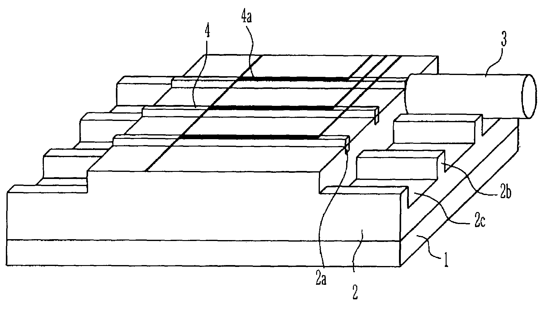
[0027]The present invention provides an optical coupling device based on a narrow-pitch multi-channel optical fiber array and a master used in fabricating the same. The optical coupling device is designed so that the dynamic stability of the optical fiber array is increased to improve the optical coupling efficiency with the optical waveguide and the multi-step master is designed to be easily and precisely fabricated. The present invention can efficiently reduce the fabricating cost by fabricating the optical coupling device by the hot embossing process using the multi-step master.

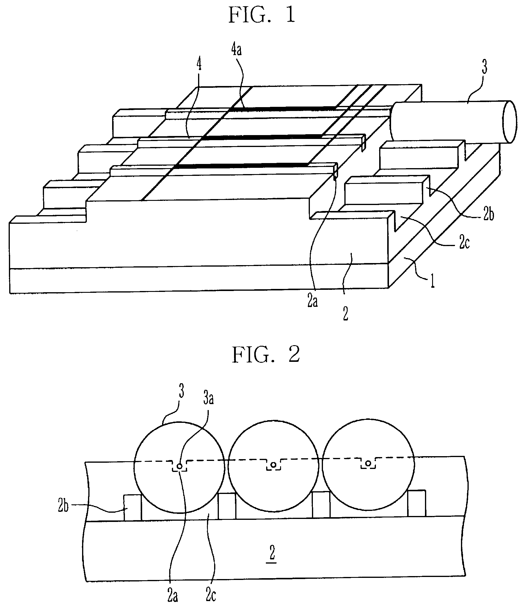
[0028]In the present invention, in order to secure the dynamic stability of the optical fiber array, a fixing projection is formed in the optical fiber aligning portion to prevent the rolling of the optical fiber. Accordingly, the optical alignment between the optical waveguide and the optical fiber can be manually performed, thereby the cost required for the alignment is reduced and the alignment error du...


PUM


Abstract

An integrated type optical coupling device capable of easily accurately performing an optical arrangement between a narrow-pitch multi-channel optical waveguide and an optical fiber array and a master used in fabricating the same are provided. By forming a fixing projection between the optical fibers, the dynamic stability of the optical fiber array is increased and the optical arrangement between the optical waveguide and the optical fiber is easily accurately performed by hand. Accordingly, the cost required for the alignment is reduced and the alignment error due to the rolling of the optical fiber is not generated. In addition, the multi-step metal master is fabricated by using a photoresist film for X-ray exposure, and the narrow-pitch multi-channel optical coupling device is fabricated in a hot embossing method using the same, thereby the high-integrated device can be fabricated at a low price.

Description

BACKGROUND OF THE INVENTION[0001]1. Field of the Invention[0002]The present invention relates to an optical coupling device and a master used in fabricating the optical coupling device, more particular, to an integrated type optical coupling device and a master used in fabricating the optical coupling device that an optical alignment between a narrow-pitch multi-channel optical waveguide and an optical fiber array can be easily accurately performed and the fabricating cost thereof can be reduced.[0003]2. Description of the Prior Art[0004]Recently, as an information communication industry is developed, data transmission using a communication network such as Internet is actively increased, thereby large scale, high speed, and high density of a transmission / exchange system for increasing the transmitting amount and the transmitting speed of data has been demanded. According to the demand, the research for integrating the channel to 40 channels greater than the existing 8 or 16 channels...

Claims


Application Information

Patent Timeline
Patent Type & Authority Patents(United States)
IPC IPC(8): G02B6/30G02B6/36
CPCG02B6/30G02B6/3636G02B6/3696G02B6/3688G02B6/3652
Inventor KIM, JIN TAEKIM, BYEONG CHEOLJEONG, MYUNG YUNG
Owner ELECTRONICS & TELECOMM RES INST
Why Eureka
Try Eureka