Lens barrel incorporating the rotation transfer mechanism

a technology of rotation transfer mechanism and lens barrel, which is applied in the direction of mountings, camera body details, instruments, etc., can solve the problems of difficult miniaturization affecting the operation of the rotation transfer mechanism, and increasing the axial length of this single rotatable member, so as to achieve a high level of rotation transfer performance

Inactive Publication Date: 2006-03-07
ASAHI KOGAKU KOGYO KK
View PDF136 Cites 52 Cited by
  • Summary
  • Abstract
  • Description
  • Claims
  • Application Information

AI Technical Summary

Benefits of technology

[0005]The present invention provides a small rotation transfer mechanism with a high level of rotation transfer performance, provided in a lens barrel, which incorporates a rotatable ring unit that is constructed as a combination of a plurality of rotatable rings and that includes one or more rotation transfer groove.

Problems solved by technology

Such gaps may interfere with a rotation transfer operation of the rotation transfer mechanism.
On the other hand, in a rotation transfer mechanism using a rotatable member constructed as a combination of a plurality of rotatable rings which are coupled to each other to serve a single rotatable ring unit, if a set of straight grooves (serving as rotation transfer grooves) extending in the optical axis direction are formed only on one of the plurality of rotatable rings, the axial length of this single rotatable member increases in accordance with the axial lengths of the straight grooves, which makes it difficult to miniaturize the rotation transfer mechanism.

Method used


Image

  • Lens barrel incorporating the rotation transfer mechanism
  • Lens barrel incorporating the rotation transfer mechanism
  • Lens barrel incorporating the rotation transfer mechanism

Examples


Embodiment Construction

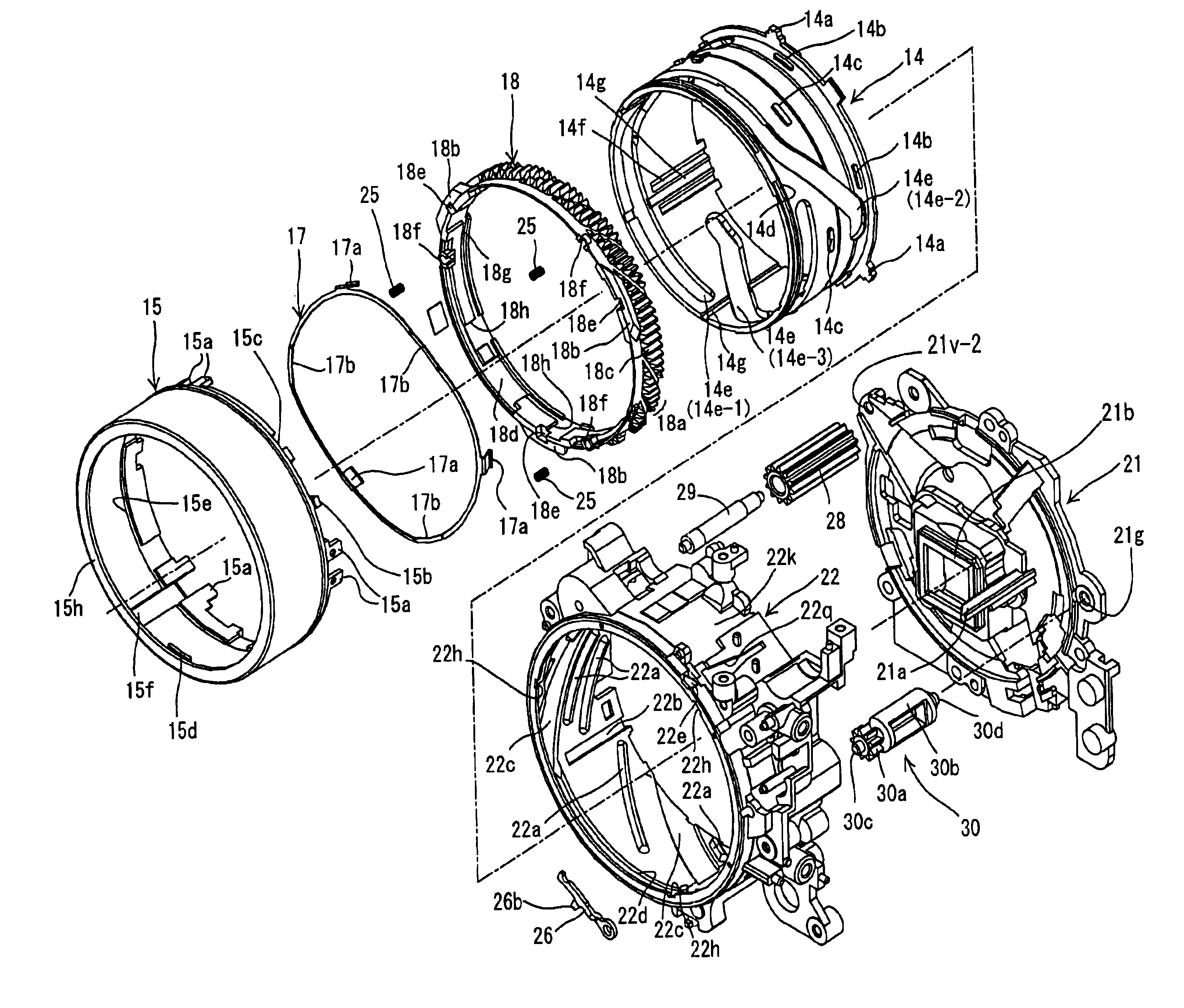
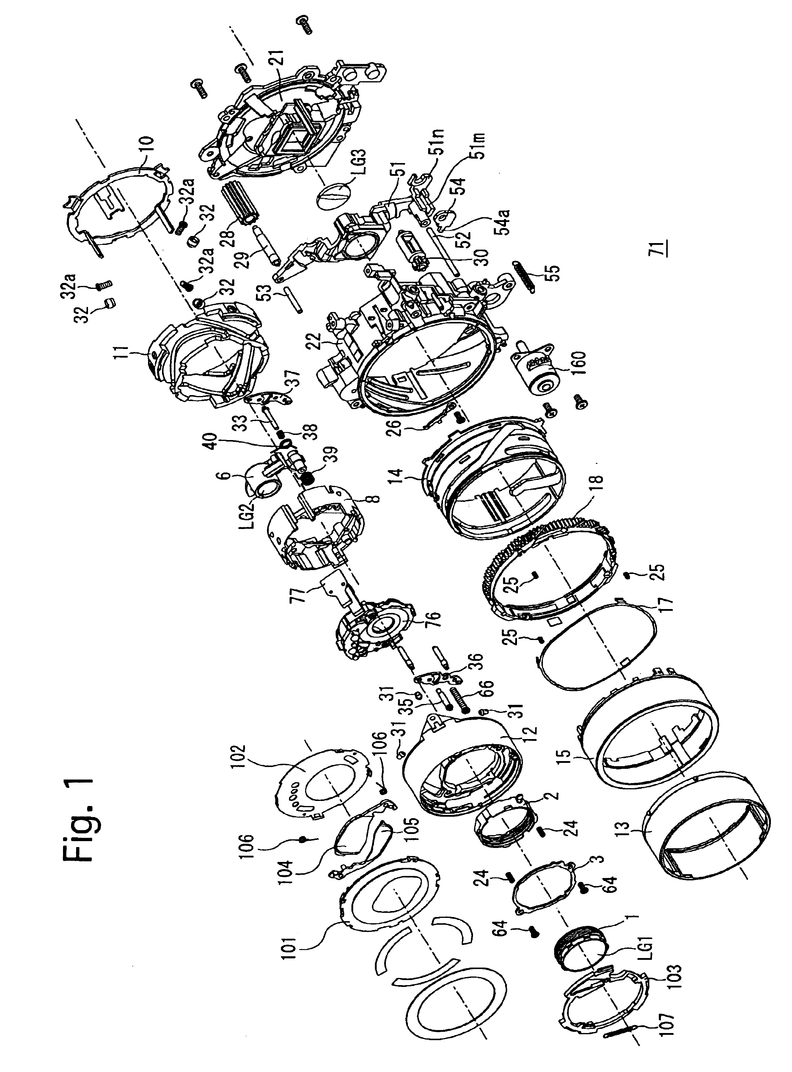
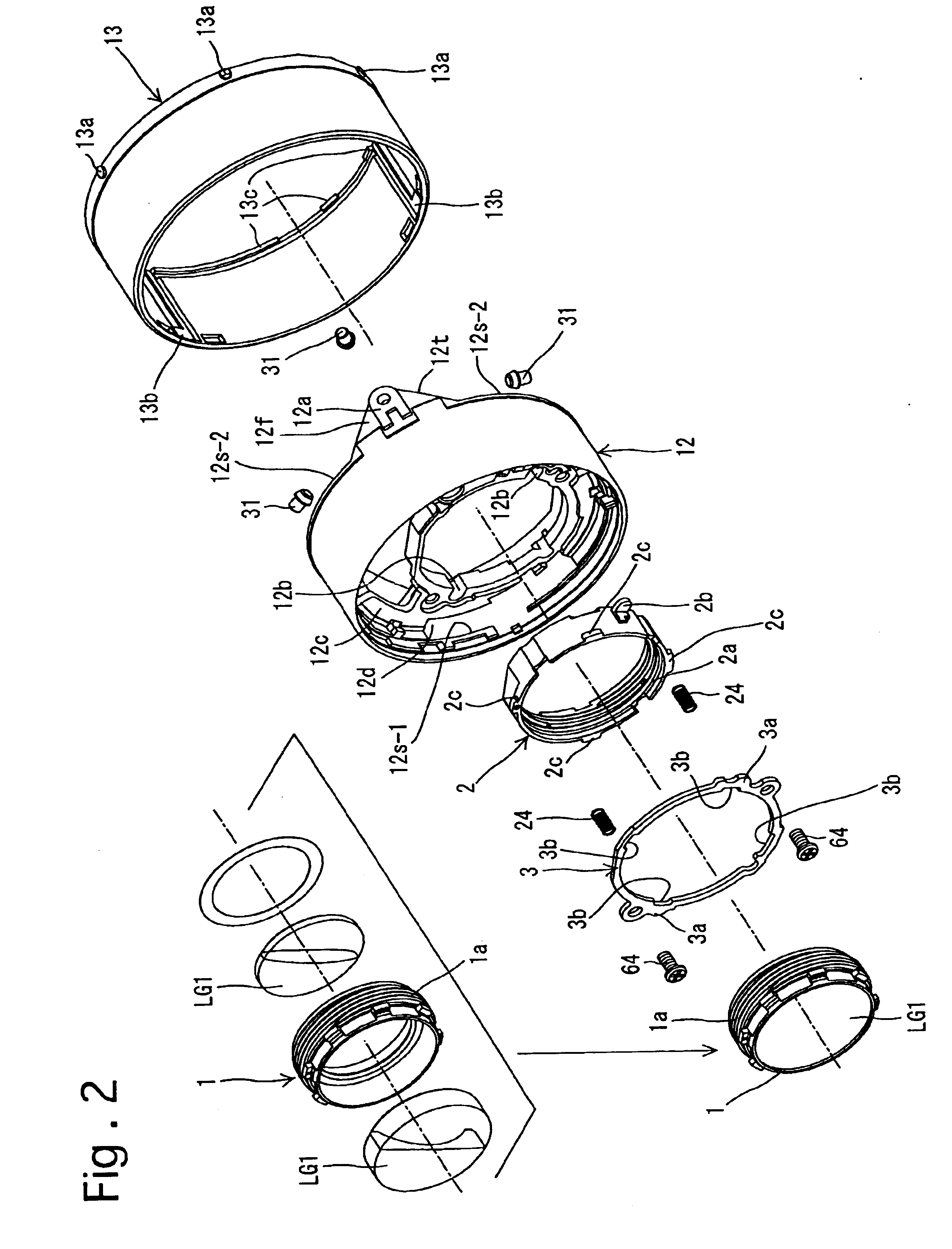
[0174]In some of the drawings, lines of different thicknesses and / or different types of lines are used as the outlines of different elements for the purpose of illustration. Additionally, in some cross sectional drawings, several elements are shown on a common plane, though positioned in different circumferential positions, for the purpose of illustration.

[0175]In FIG. 22, the symbols “(S)”, “(L)”, “(R)” and “(RL)” which are each appended as a suffix to the reference numeral of some elements of a present embodiment of a zoom lens (zoom lens barrel) 71 (see FIGS. 5 through 10) indicate that the element is stationary, the element is solely movable linearly along a lens barrel axis Z0 (see FIGS. 9 and 10) without rotating about the lens barrel axis Z0, the element is rotatable about the lens barrel axis Z0 without moving along the lens barrel axis Z0, and the element is solely movable along the lens barrel axis Z0 while rotating about the lens barrel axis Z0, respectively. Additionally...


PUM


Abstract

A rotation transfer mechanism of a lens barrel includes a pair of rotatable rings, adjacent ends of which are opposed to each other; an axial-direction projection extending in the rotational axis direction; an axial-direction recess in which the axial-direction projection is positioned; a rotation transfer groove located on an inner peripheral surface of the one of the rotatable rings that has the axial-direction projection, wherein a circumferential position of the rotation transfer groove corresponds to a circumferential position of the axial-direction projection; a driven rotational member having a rotation transfer protrusion engaged in the rotation transfer groove, the rotation transfer protrusion slidably movable in the rotation transfer groove in the rotational axis direction and configured to transmit rotation of the rotatable ring to the driven rotational member; and at least one optical element configured to be driven by the driven rotational member.

Description

BACKGROUND OF THE INVENTION[0001]1. Field of the Invention[0002]The present invention relates to a lens barrel incorporating a rotation transfer mechanism for transmitting a rotation of a rotatable ring to a driven rotational member.[0003]2. Description of the Related Art[0004]Lens barrels which incorporate a rotation transfer mechanism using two rotatable members that are movable in an rotational axis direction relative to each other and rotatable together at all times in a rotational direction are known in the art. A typical structure of such a rotation transfer mechanism is such that one of the two rotatable members is provided with a set of straight grooves (serving as rotation transfer grooves) extending in the rotational axis direction while the other rotatable member is provided with a corresponding set of protrusions (serving as rotation transfer protrusions) such as a set of rollers which are respectively engaged in the set of straight grooves to be slidably movable thereal...

Claims


Application Information

Patent Timeline
Patent Type & Authority Patents(United States)
IPC IPC(8): G03B17/00G02B7/00G02B7/02G02B7/08G02B7/10G02B15/14
CPCG02B7/022G02B7/026G02B15/14G02B7/102G02B7/08G02B15/143G02B7/04G03B2217/00
Inventor NOMURA, HIROSHI
Owner ASAHI KOGAKU KOGYO KK
Why Eureka
Try Eureka