Tool wear monitoring system

Inactive Publication Date: 2006-03-07
MCDONNELL RYAN P +1
View PDF31 Cites 37 Cited by
  • Summary
  • Abstract
  • Description
  • Claims
  • Application Information

AI Technical Summary

Benefits of technology

[0014]In accordance with still yet a further aspect of the invention, a monitoring device for monitoring at least one cycling manufacturing machine having a plurality of component tools is provided. The monitoring device includes a counter, a processor, and at least one visual indicator corresponding to at least one cycling manufacturing machine. The visual indicator is in operative communication with the processor and includes first, second, and third indicia corresponding to a status of the cycling machine. The first indicia corresponds to the at least one cycling machine having one or more than one threshold

Problems solved by technology

However, materials processing machines typically involve cutting and/or abrasive interaction between the component tools or tool inserts and the work piece.
This cutting and/or abrasion eventually results in a dulling of the tool cutting surfaces or other tool degradation which is usually correctable by sharpening the affected tool.
An unanticipated shutdown, such as due to a catastrophic tool failure, can shut down operations at an inopportune time, e.g. when a delivery deadline is approaching.
Furthermore, replacement of tools on a schedule determined by the tool manufacturer's recommendation and/or past experience of the manufacturing site greatly reduces the likelihood of producing defective parts due to sub-standard or non-optimized machine tool performance.
Lastly, overused and/or broken tooling usually cannot be simply resharpened and must be replaced at a typically large expense.
Although the benefits of scheduled tool replacements are well recognized in industry, a problem arises in projecting the timing of such replacements and, thereafter, actually exercising the replacement.
However, knowledge of

Method used


Image

  • Tool wear monitoring system
  • Tool wear monitoring system
  • Tool wear monitoring system

Examples


Embodiment Construction

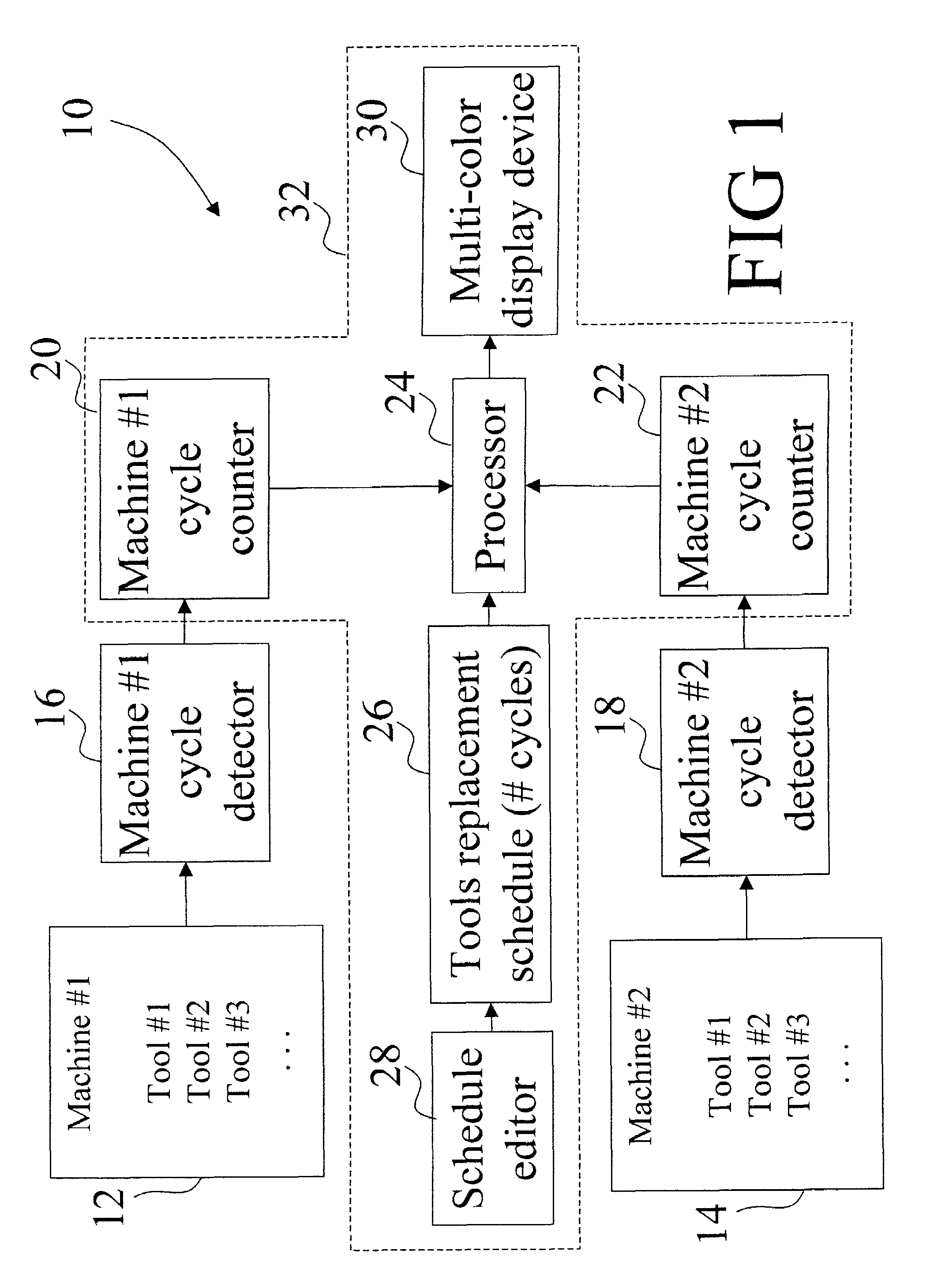
[0031]With reference to FIG. 1, an apparatus 10 for monitoring the status of a plurality of machines 12, 14 at a manufacturing site is shown. The machines 12, 14 can be of any type, for example, they may be single- or multiple-spindle automatic screw machines, dial index / rotary transfer machines, transfer lines, or the like. Although two machines are shown in FIG. 1, it will be recognized that the invention is compatible with an arbitrary number of machines.

[0032]Each machine 12, 14 typically includes a plurality of component tools that cut, drill, turn, grind, thread, form, or otherwise work, process, or modify a workpiece. Each machine 12, 14 operates on a cyclic basis in which each machine cycle typically produces a single part. In an industrial environment, an important consideration is maximizing throughput of such machinery. Hence, the machines 12, 14 preferably operate essentially continuously, each at a substantially steady operating rate, uninterrupted except for periodic m...


PUM


Abstract

A monitoring apparatus for monitoring one or more manufacturing machines having a plurality of component tools and engaged in repetitive machining of a part is provided. An input device detects occurrence of a machine cycle. A counter stores the number of detected machine cycles as a count value. A machine speed processor estimates a temporal rate at which the machine cycles occur. A data storage device stores a maintenance schedule indicating the number of machine cycles between recommended replacements for each tool. A tools processor estimates a remaining operating time for each tool before scheduled replacement. A machine viability processor estimates a remaining operating time for the machine before schedule replacement of each of the component tools. A display device displays the operating time for the machine before scheduled replacement of each of the component tools. A method for monitoring a cycling manufacturing machine includes detecting machine cycles of the manufacturing machine, estimating a machine operating rate based on the detecting step over time, and projecting tool change times for each of the plurality of tools based on the estimated machine operating rate and pre-selected tool cycle lifetime values for each of the plurality of tools.

Description

BACKGROUND OF THE INVENTION[0001]The invention relates to automated manufacturing. It particularly relates to the monitoring of automated machine tools in process lines, manufacturing sites and other industrial settings, and will be described with particular reference thereto. However, the invention also finds application in other automated manufacturing processes where prompt scheduled maintenance or replacement of components of the manufacturing equipment is advantageous.[0002]Typical materials processing lines or manufacturing sites include a plurality of machines, each performing one or more processing steps. The machines can, for example, be single- or multiple-spindle automatic screw machines, dial index / rotary transfer machines, transfer lines, or the like. Each machine in the process line typically includes a plurality of specialized tools that cut, drill, turn, polish, or otherwise work, process, or modify a work piece. Each machine usually operates on a cyclic basis system...

Claims


Application Information

Patent Timeline
IPC IPC(8): G06F19/00G05B19/4065
CPCG05B19/4065G05B2219/37252G05B2219/37229Y02P90/80
Inventor MCDONNELL, RYAN P.MCDONNELL, TIMOTHY R.
Owner MCDONNELL RYAN P
Why Eureka
Try Eureka