Method for anchoring parallel wire cables and suspension system for a construction work

a technology of suspension system and parallel wire, which is applied in the direction of construction, structural elements, building components, etc., can solve the problem of compact anchorage and other problems

Inactive Publication Date: 2006-03-14
FREYSSINET INT STUP
View PDF31 Cites 31 Cited by
  • Summary
  • Abstract
  • Description
  • Claims
  • Application Information

AI Technical Summary

Benefits of technology

[0011]In view of these problems, an object of the present invention is to provide a method making it possible to

Problems solved by technology

The resulting anchorag

Method used


Image

  • Method for anchoring parallel wire cables and suspension system for a construction work
  • Method for anchoring parallel wire cables and suspension system for a construction work
  • Method for anchoring parallel wire cables and suspension system for a construction work

Examples


Embodiment Construction

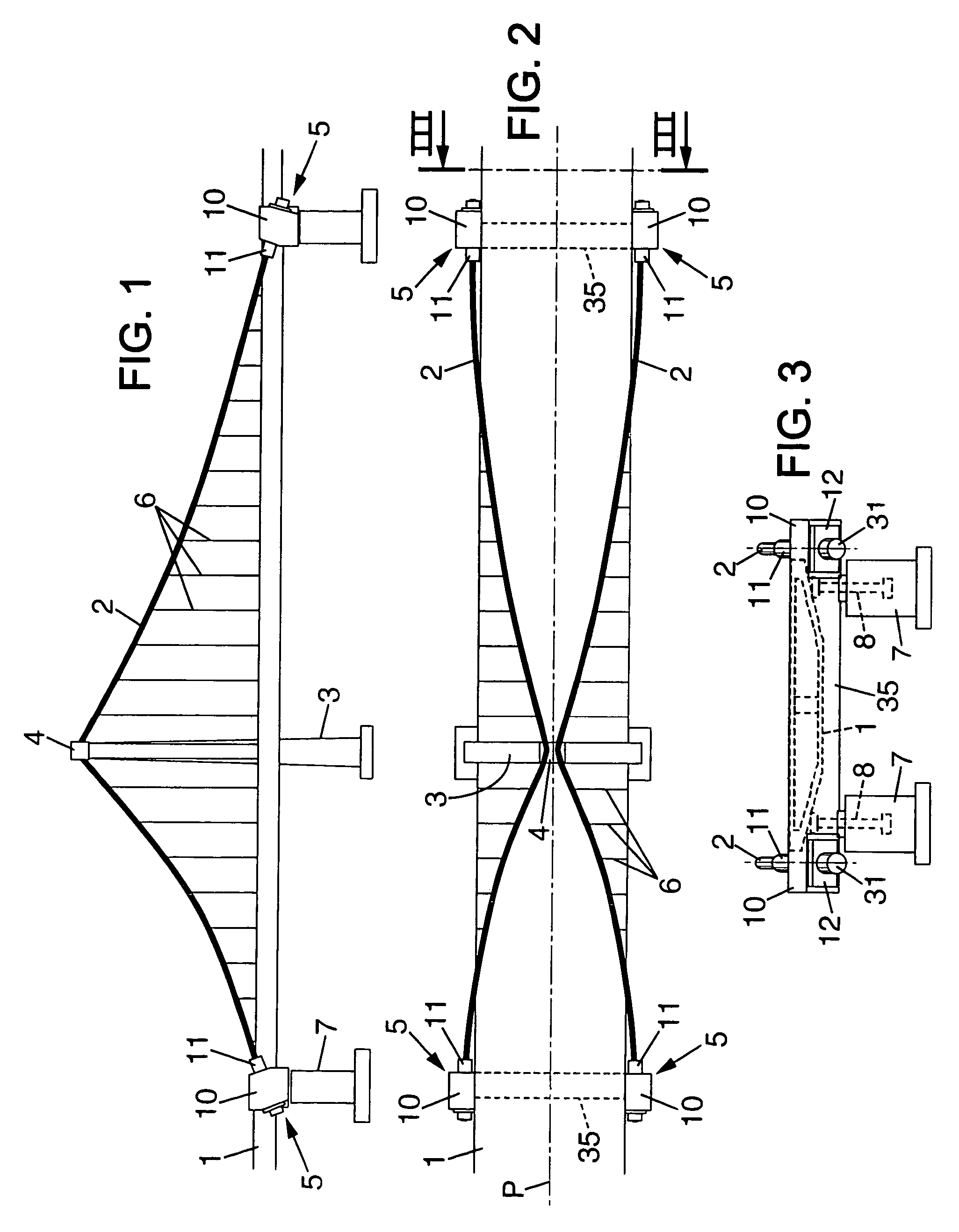
[0027]The bridge shown in FIGS. 1–3 has a section constructed as a suspension bridge of the self-anchored type with a single pylon 3.

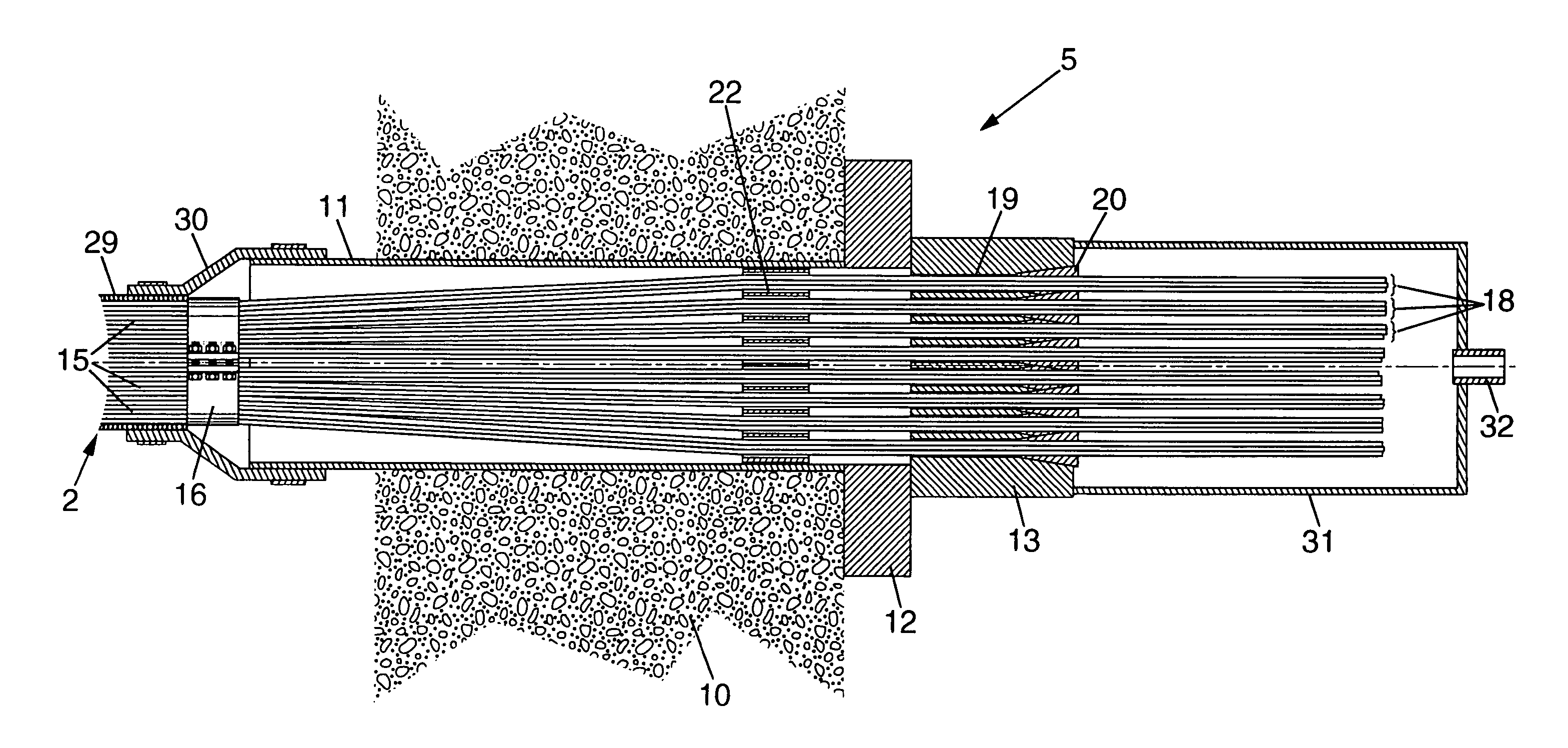
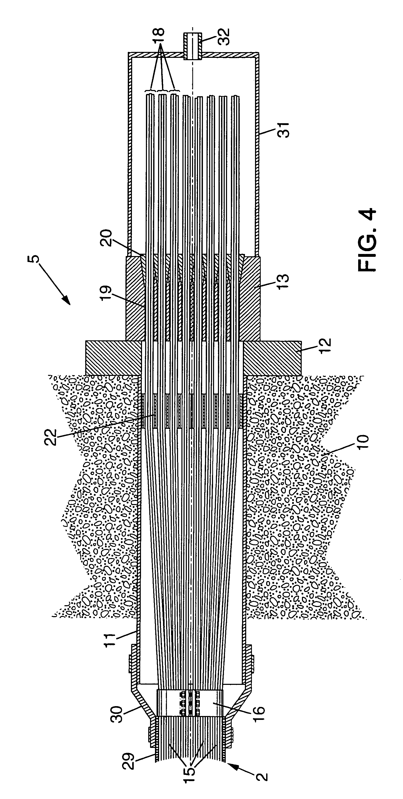
[0028]In that section, the deck 1 is supported by means of main suspension cables 2 arranged symmetrically on both sides of a vertical plane P located in the middle of the deck (FIG. 2). Each suspension cable 2 is deviated on a saddle 4 mounted on top of the pylon 3. Its both ends are anchored on the deck 1 by means of respective anchoring systems 5. Between the pylon 3 and each anchorage 5, a set of hangers 6 are attached to the main suspension cable 2 at their upper end, and to the deck 1 at their lower end. The hangers 6 transmit the load of the deck 1 to the main cables 2.

[0029]Piers 7 are erected under the deck 1 in the region of the anchorage systems 5 of the main cables. As shown diagrammatically in FIG. 3, tie-down cables or bars 8 are fixed to each pier 7 and to the deck 1. These tie-down members 8 are designed to take up the vertical componen...


PUM


Abstract

The structural cable (2) to be anchored, such as a main suspension cable or a stay cable, is made of a compact bundle of parallel metallic wires. The cable wires are distributed into seven-wire units (18) in a portion of the cable adjacent to an anchor block (13), and these seven-wire units are individually anchored on the anchor block.

Description

BACKGROUND OF THE INVENTION[0001]The present invention relates to the use of structural cables in construction works such as bridges. In particular, the invention is applicable to suspension bridges and cable-stayed bridges.[0002]In a suspension bridge, the deck is supported via hangers attached to one or more main suspension cables. Each suspension cable is anchored at both ends and deviated on one or more pylons erected along the bridge span. In a cable-stayed bridge, the deck is supported by a set of cables, called stays, each extending between a pylon and an anchorage mounted on the deck.[0003]In most suspension bridges, the main suspension cables usually consist of a bundle of parallel metallic wires arranged side by side in a compact configuration. It has also been proposed to build the main suspension cables from seven-wire strands, each strand having six peripheral wires twisted around a central wire (see e.g. EP-A-0 950 762). Such strand is advantageously surrounded by a pl...

Claims


Application Information

Patent Timeline
IPC IPC(8): E01D19/16E01D11/00E01D19/14
CPCE01D19/14E01D11/00
Inventor STUBLER, JEROMEMCCLENAHAN, MIKEZIVANOVIC, IVICA
Owner FREYSSINET INT STUP
Why Eureka
Try Eureka